Parts List
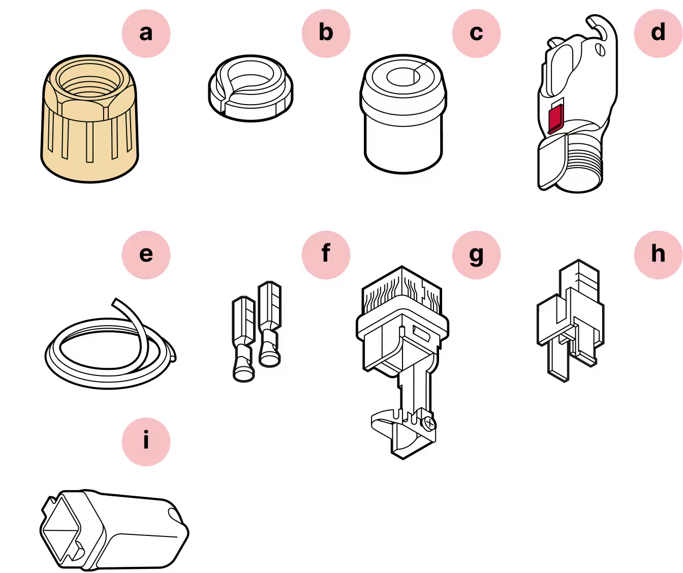
- a
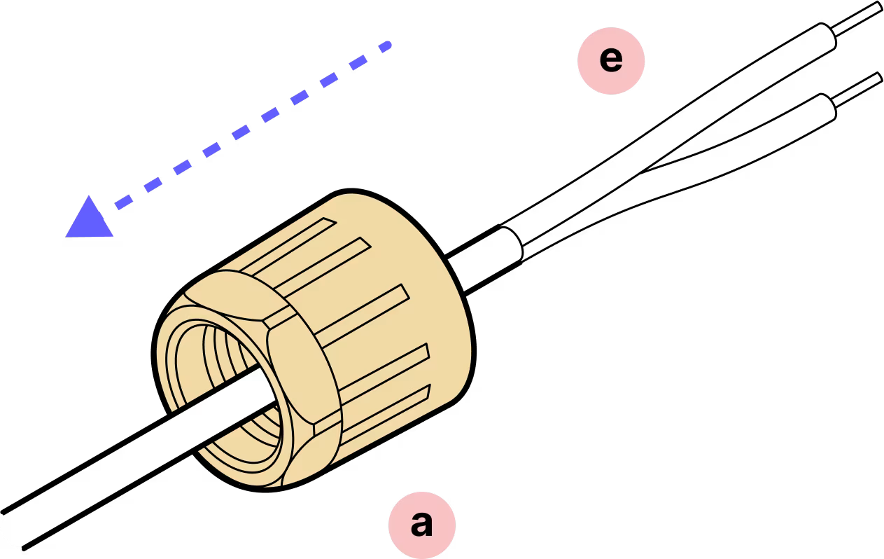
Yellow gland nut
- b
Tightening cone
- c
Split rubber gland
- d
Housing
- e
DC cable (not provided)
- f
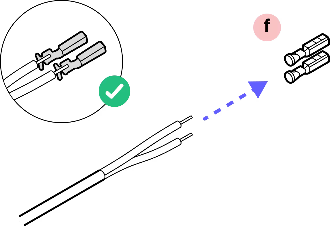
Crimp contacts
- g
Cable holder
- h
Plastic housing
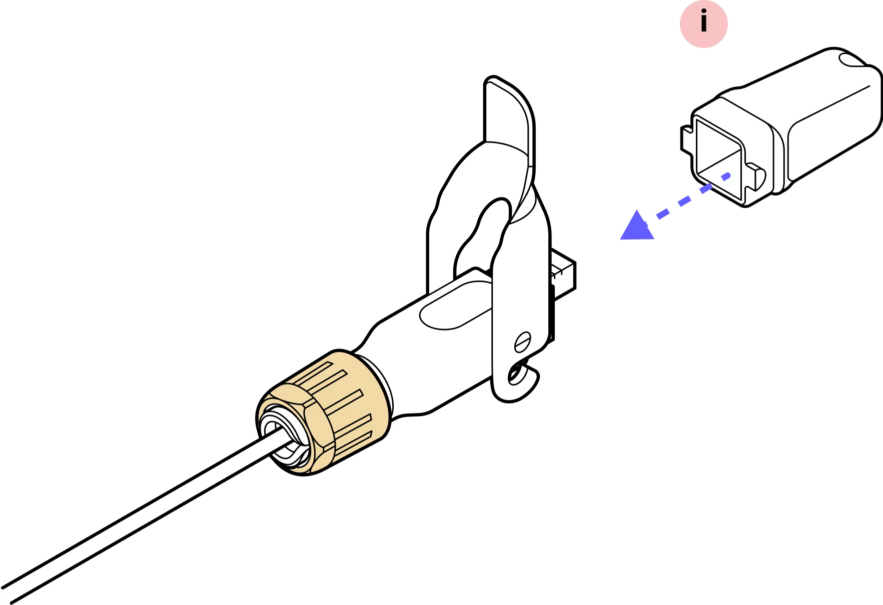
- i
Plug cap
Required Tools
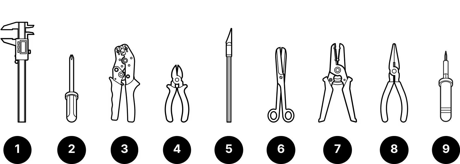
- 1
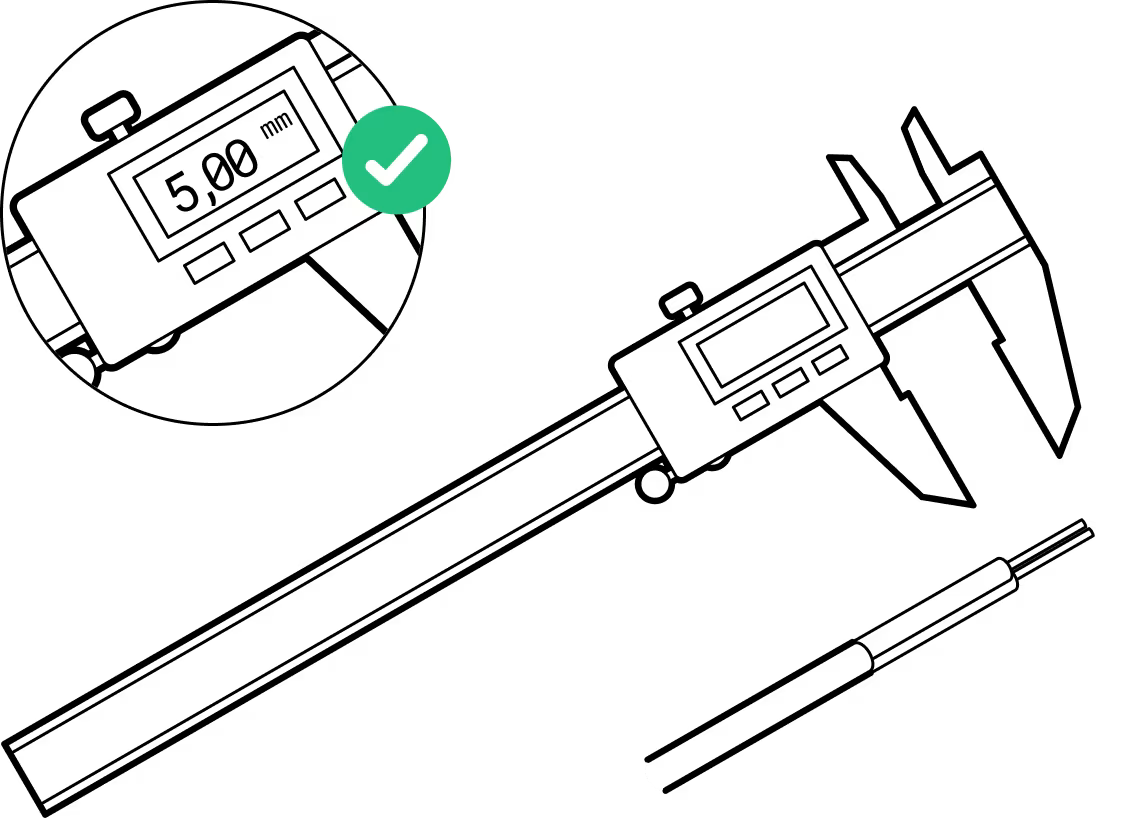
Caliper
- 2
Screwdriver
- 3
Wire crimping tool
- 4
Wire cutters
- 5
X-Acto knife
- 6
Scissors
- 7
Wire strippers
- 8
Pliers (if not using crimping tool)
- 9
Soldering iron (if not using crimping tool)
Tips:
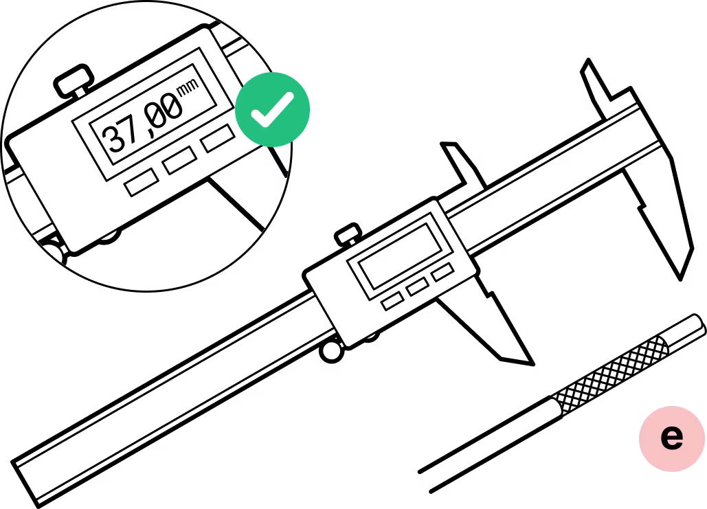
Be accurate in measurements
Wire stripping is 37mm and conductor stripping is 5mm. Try on the crimp contacts to match.
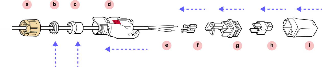
Double check the orientation
For this connector, it is very important to observe the correct orientation for the cable holder and plastic housing. Look at the arrow tips on the case and check the instructions twice before attaching the contacts.
Do not remove the dust caps from the WOC terminal until you are ready to plug in the Octis connector.
Assembly
Installation
Step 1
Remove 37mm of the outer jacket off the cable. Remove any additional padding material.
Step 2
Strip 5mm of each wire.
Step 3
Step 4
Slide the yellow gland nut onto the cable followed by the plastic housing.
Step 5
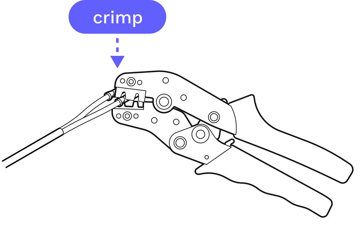
Ensure you have selected the proper crimp contact gauge for your wires.
Step 6
If pliers are used, solder the wire connections to the crimp contact to ensure a secure and reliable connection.
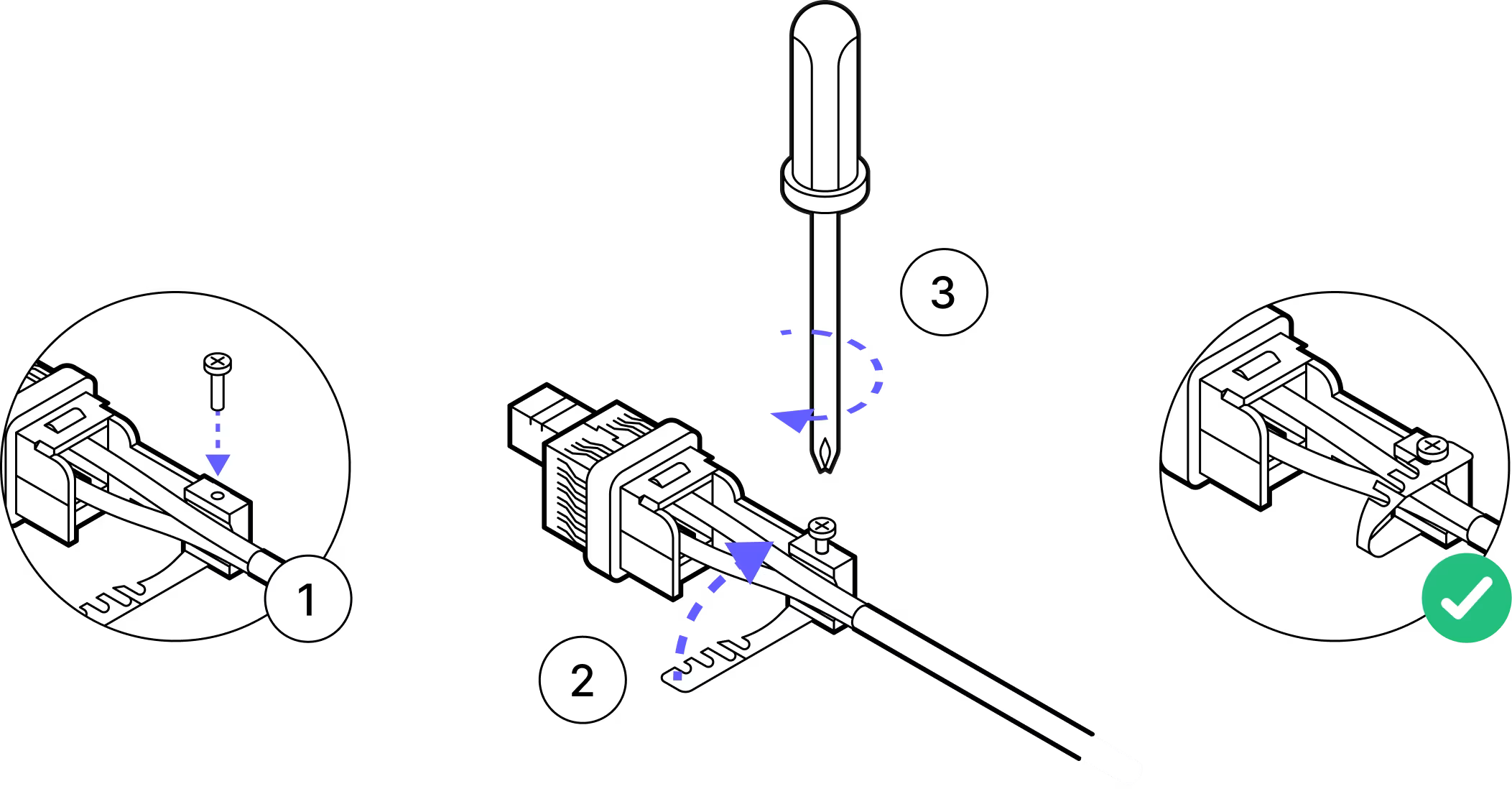
Step 7
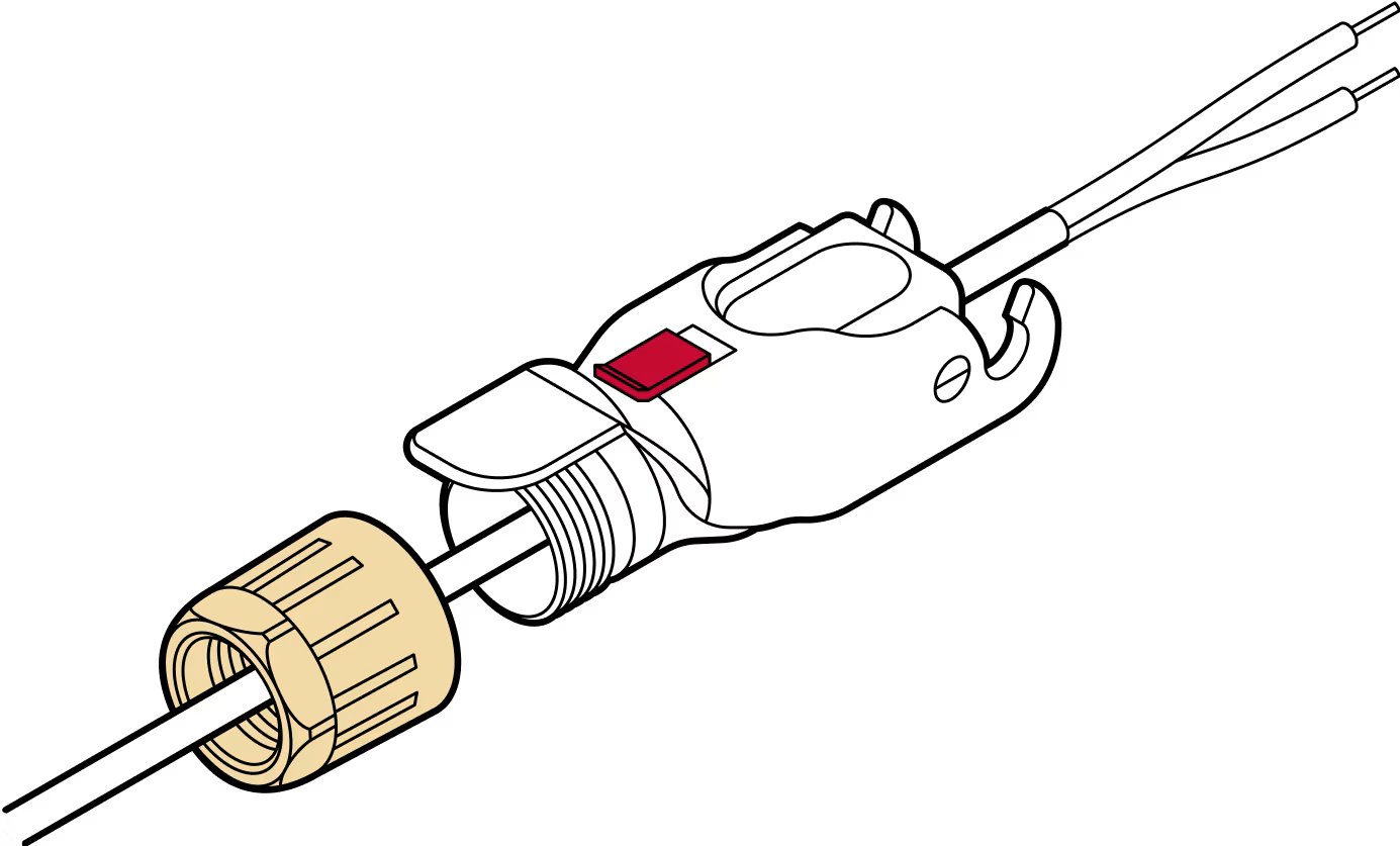
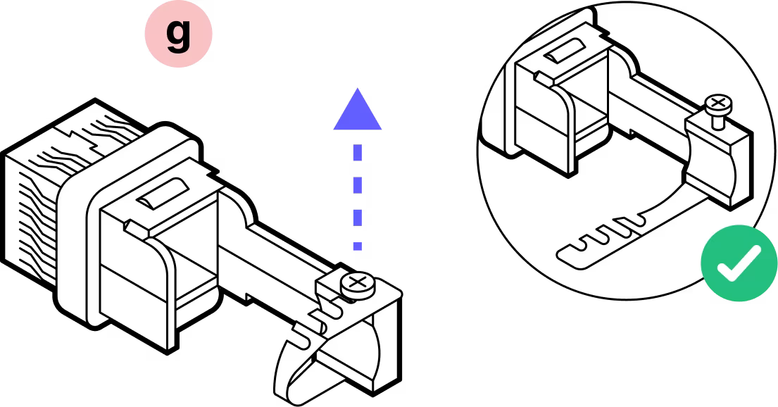
Back off the screw that holds the metal strap in place and uncurl the strap. Then slide the crimped contacts into and through the housing per the images in steps 8, 9, and 10.
Step 8

Step 9
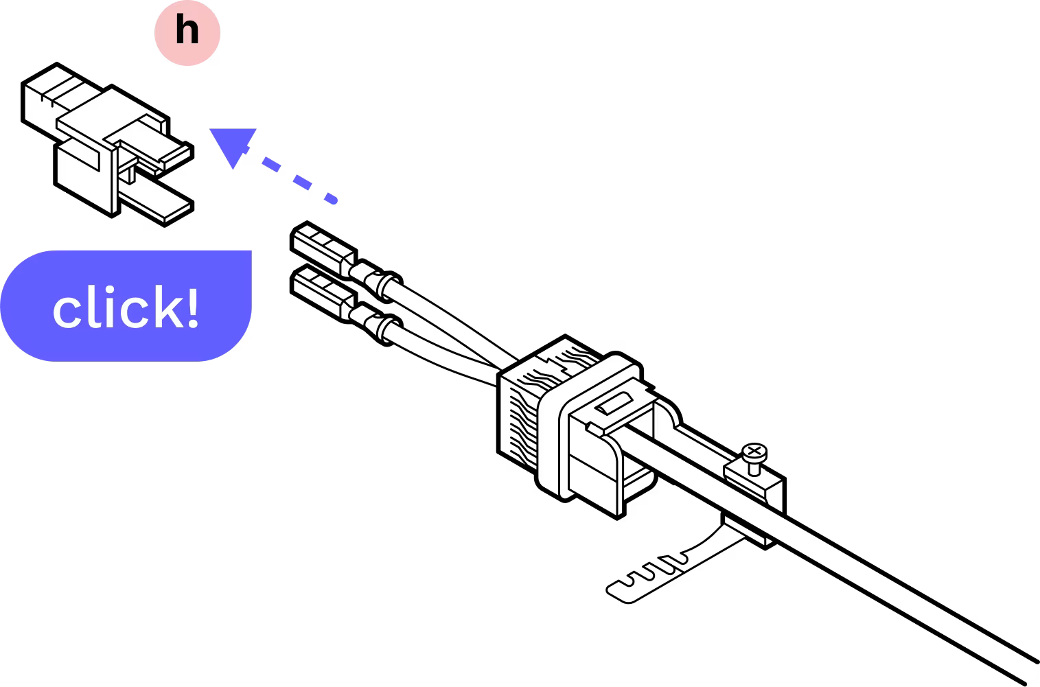
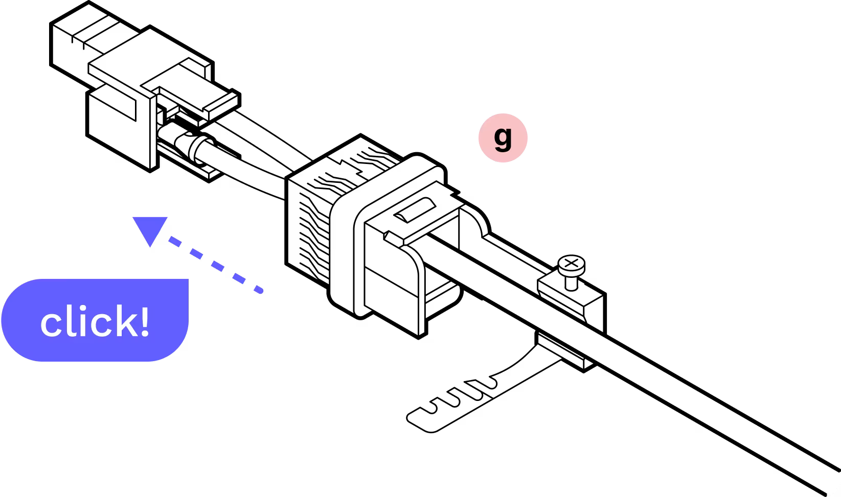
With the notch on the top of the crimp contacts and the plastic housing in the orientation shown above, slide the contacts into the housing until they click into place. It does not matter which color goes into which slot.
Step 10
Step 11
Slide the metal band into place on the screw and tighten. There is a nut visible through a window in the side of the housing. Tighten the screw until the nut is snug at the top.
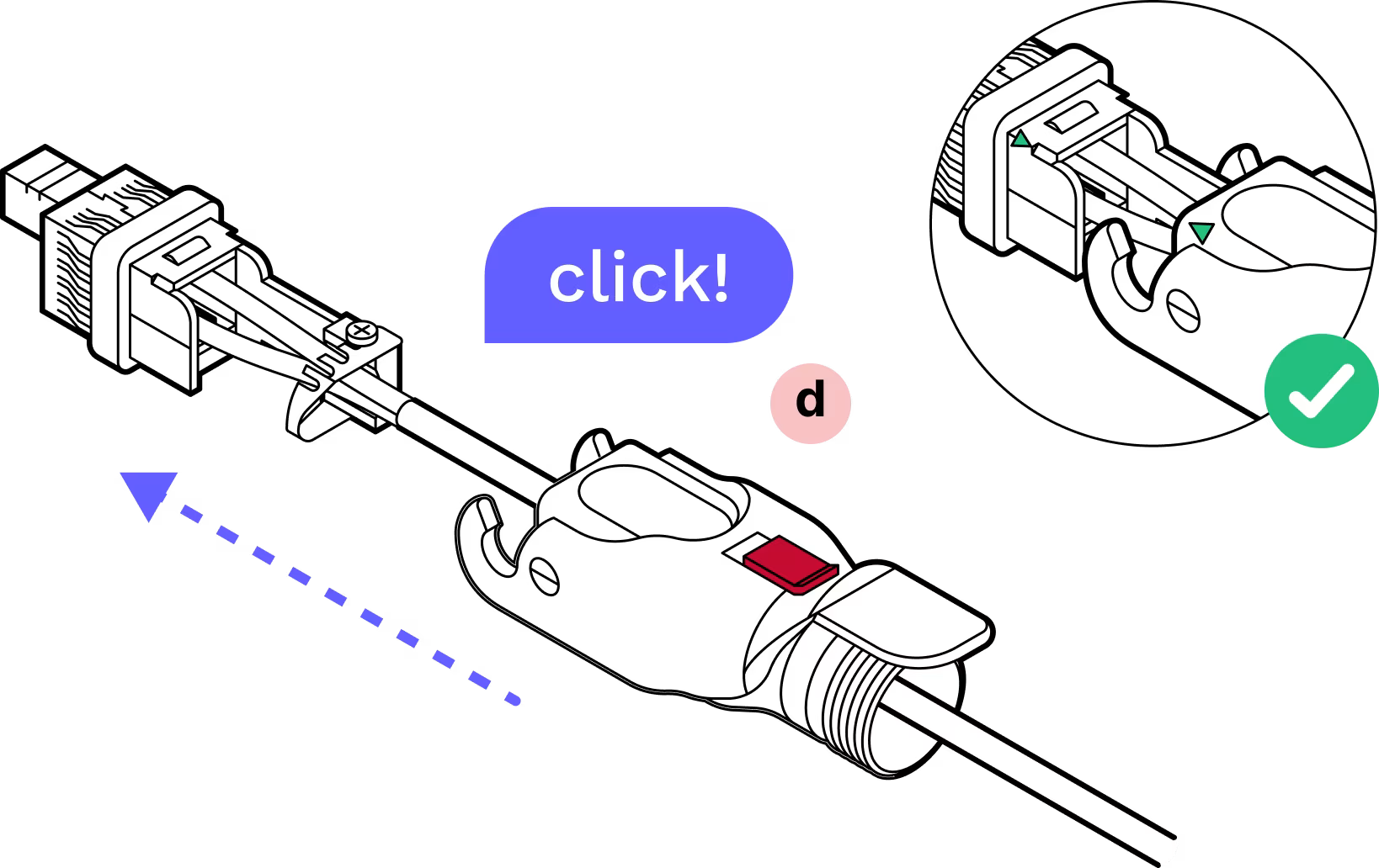
Step 12
Line up the arrow on the outer housing with the arrow on the inner housing and slide them together until they click.
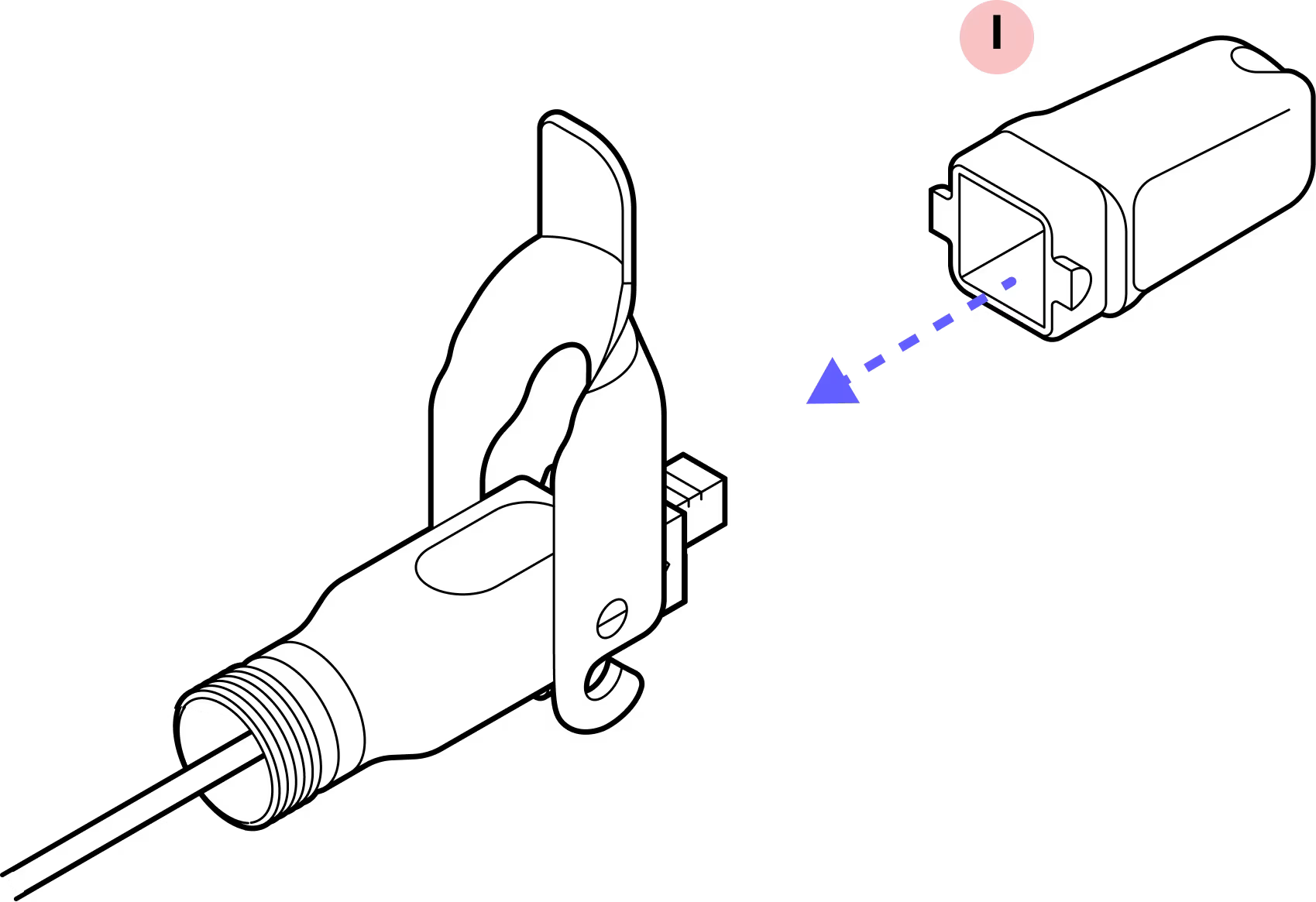
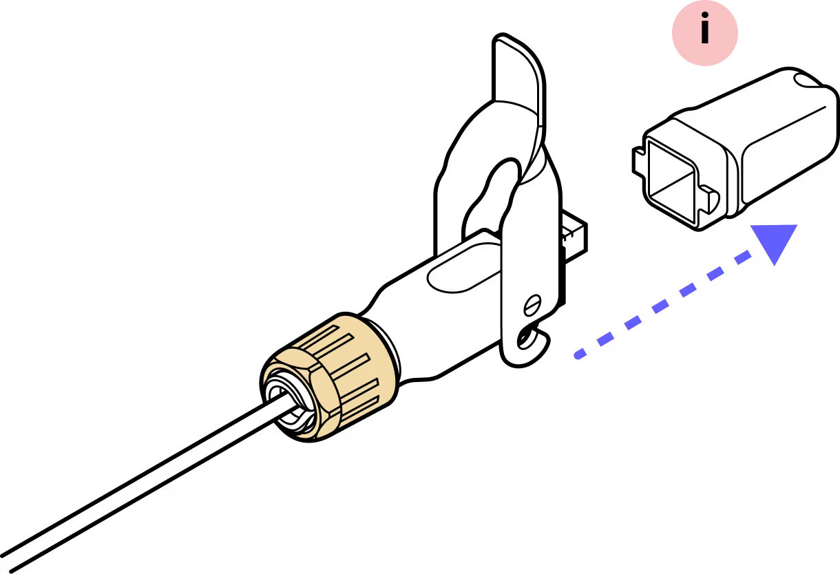
Step 13
Slide the dust cap onto the Octis connector.
Step 14
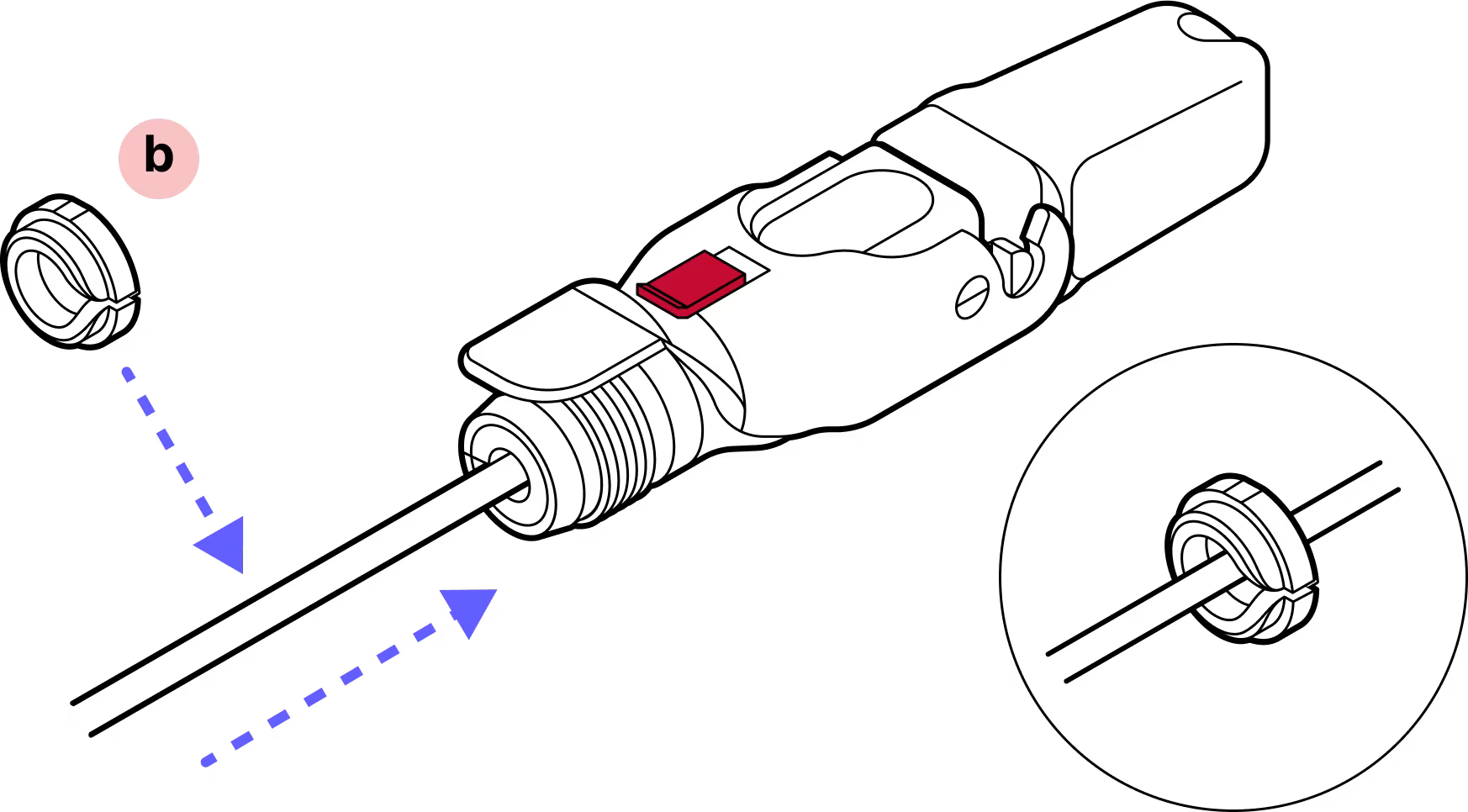
Slide the split rubber gland onto the cable and fit it snugly into the cylindrical portion of the Octis housing.
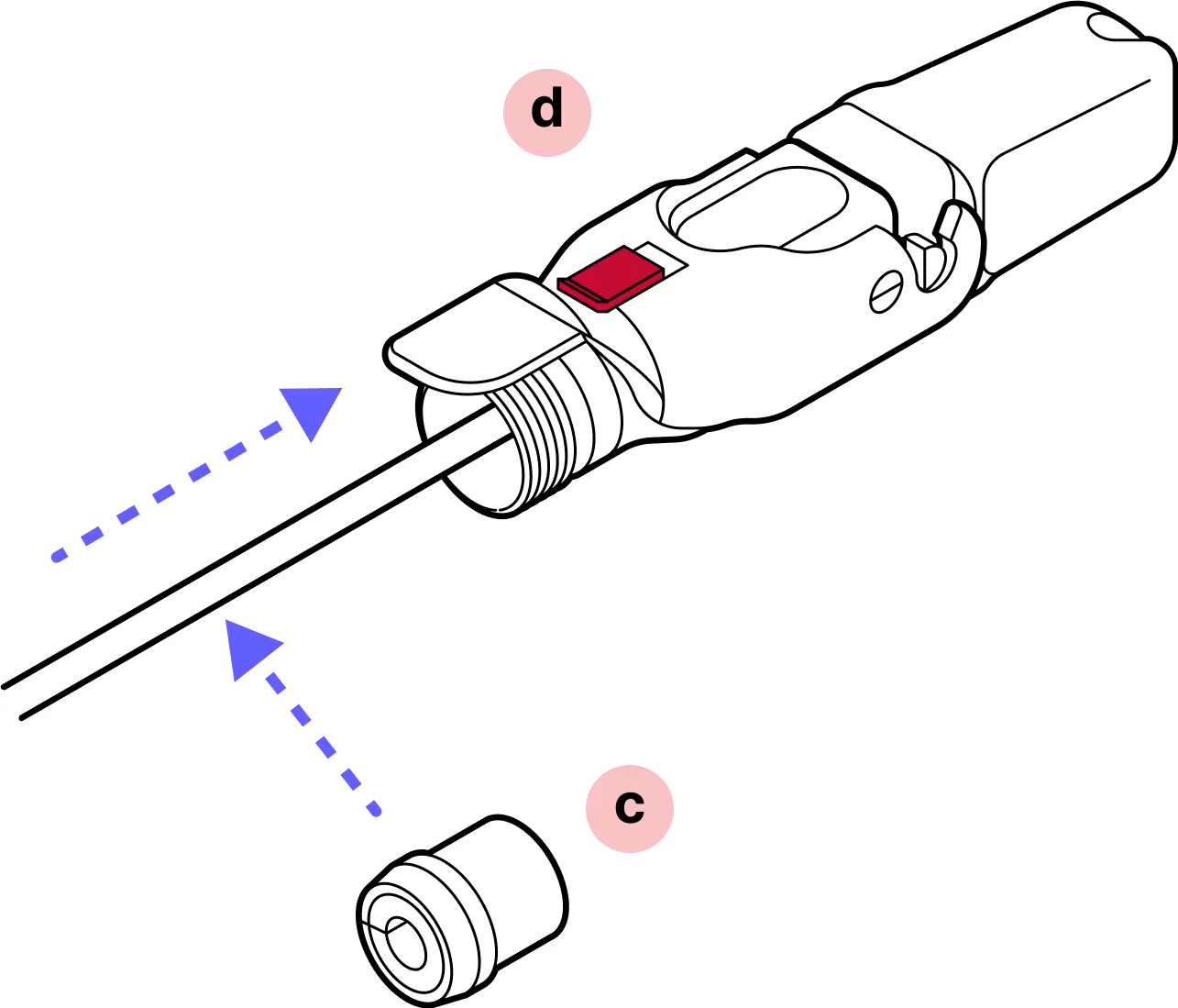
Step 15
Slide the tightening cone onto the cable and make sure it is in the proper orientation.
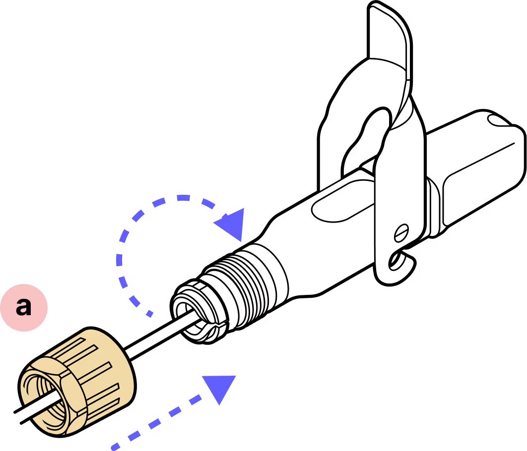
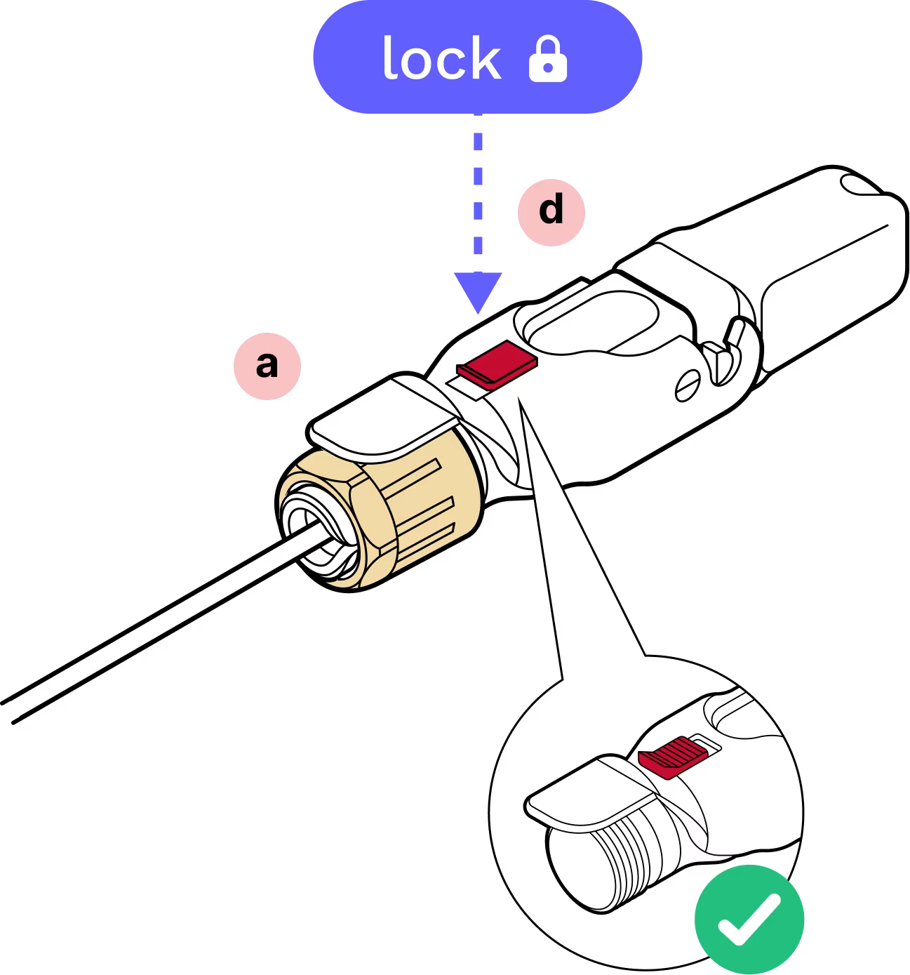
Step 16
Open the hinge lock and tighten the yellow gland nut. Note that the red slide lock locks on the rim of this nut so it must be tightened enough to catch the red slide lock when in the locked position. DO NOT OVER-TIGHTEN.
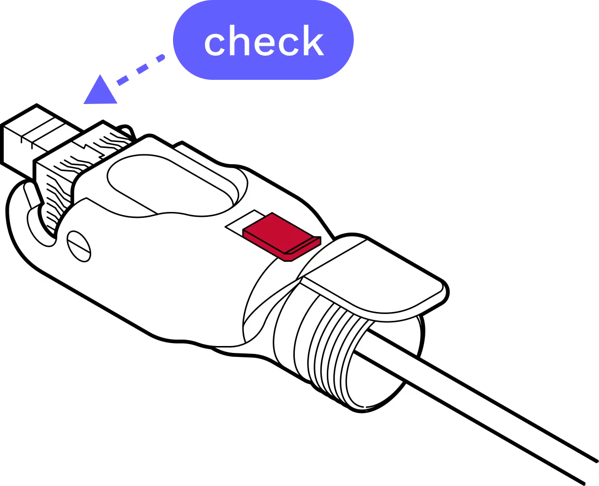
Step 17
IMPORTANT: When closing the hinged lock, the red lock MUST be in the UNLOCKED position. Do not force the hinge lock down or you may break the red slide lock.
Step 18
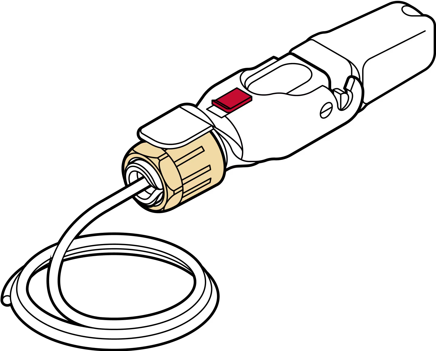
Check to make sure the housing or connectors don't push back into the housing before replacing the dust cap.
Step 19
Step 20
Complete!
Last updated: April 2026