Wireless Optical Communication (WOC) Terminal Overview
Taara uses Wireless Optical Communication (WOC), a line-of-sight technology, to transmit video, voice, and data at high speeds of up to 20 Gbps full-duplex throughput. Data is transmitted over the unlicensed optical spectrum. A single link can cover distances up to 20 km. The effective range may be increased by relaying links.
Taara's wireless links can be used to provide fiber backhaul, rapidly extend existing architecture, and create local area networks. Built for distance, Taara Lightbridge rapidly extends high-capacity connectivity from a fiber point-of-presence, without digging, stringing cables, or coordinating spectrum licenses.
Quick deployment
- Can be installed and uninstalled in a couple hours
- Easy to transport; requires limited support equipment
- May be mounted on poles, towers, or rooftops
Connectivity across difficult terrain
- Sites located around water bodies
- Forested regions
- Railway tracks and dense urban areas
No right of way permits
- No right-of-way permits or spectrum licenses
- Data is transmitted wirelessly with Class 1M eye-safe lasers in the unlicensed infrared band (193 THz)
Cost competitive and easy to integrate
- Significantly favorable economics on a cost per Gbps per km compared to traditional alternatives
- Based on open standards to work with existing infrastructure
Complete full training in Taara University.
This installation guide supports the online training and does not replace it. https://taara.team/taarauniversity
For additional support, please go to Taara Support Hub.
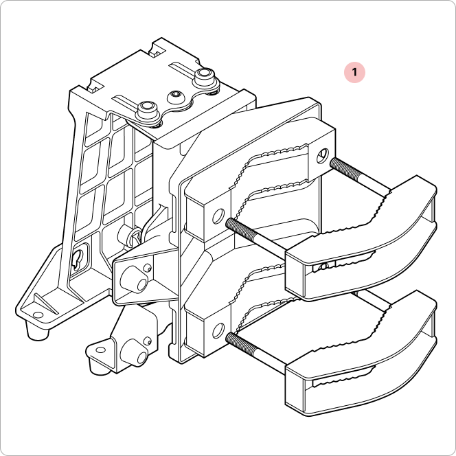
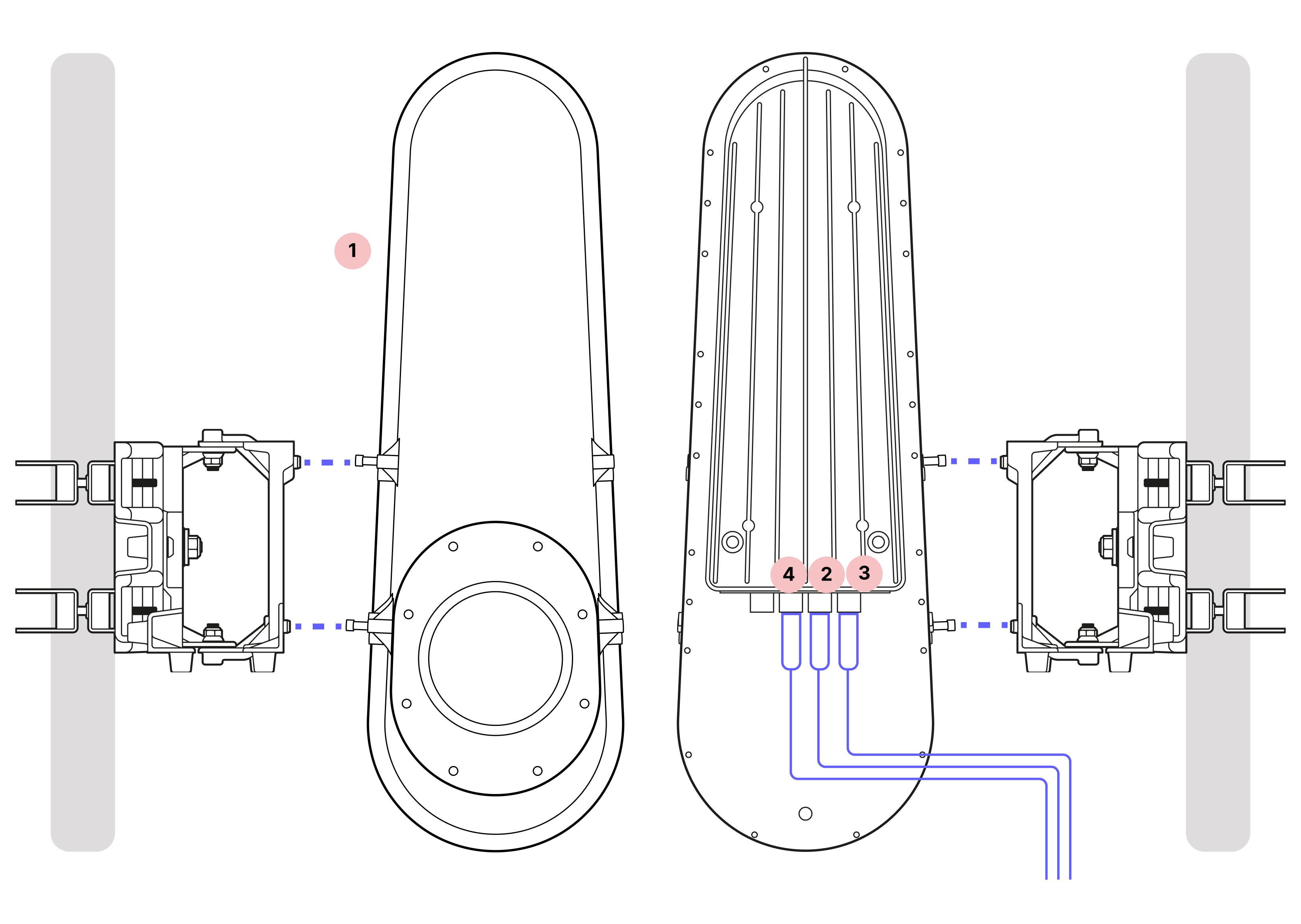
Wireless Optical Communication (WOC) Terminal Overview
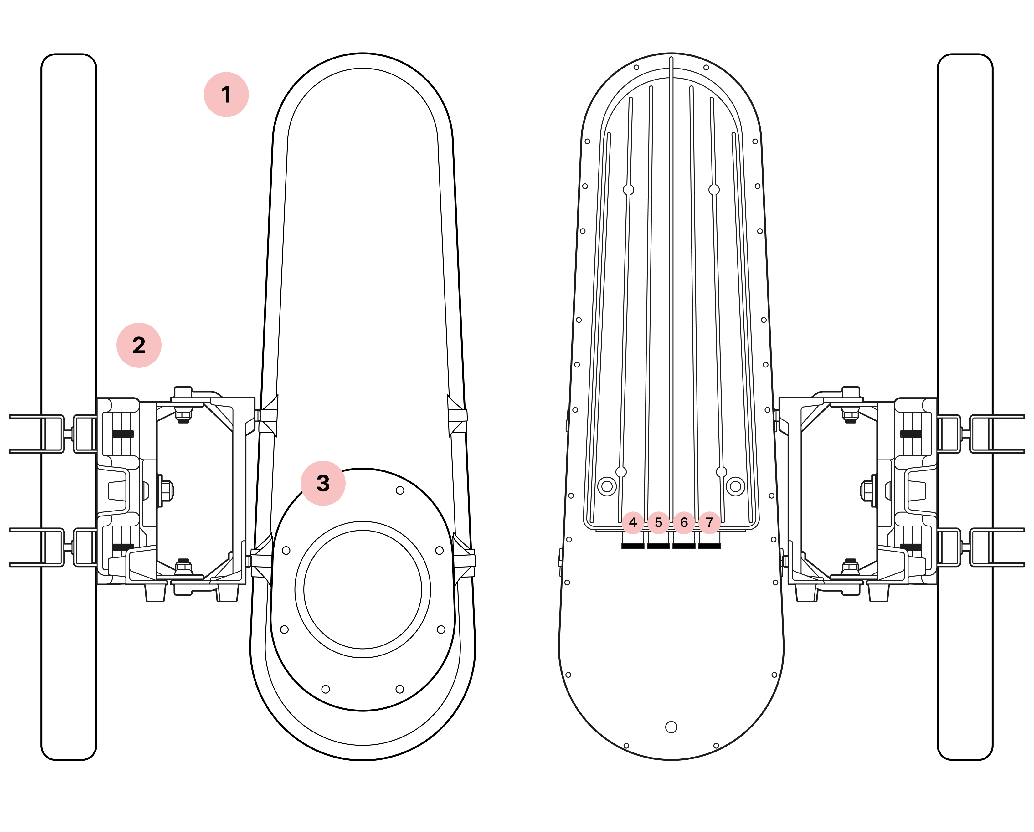
- 1
Chassis
- 2
Mounting bracket
- 3
Window
- 4
Octis SFP connector (Channel 2)
- 5
Octis SFP connector (Channel 1)
- 6
Octis RJ45 connector
- 7
Octis DC connector
1. Critical requirements
Do not remove the dust caps
Taara Lightbridge terminals feature high-grade optical components in an enclosure designed for IP65 rating. To maintain this protection, all connector ports must be covered either by the dust caps or Octis connectors properly inserted and locked.
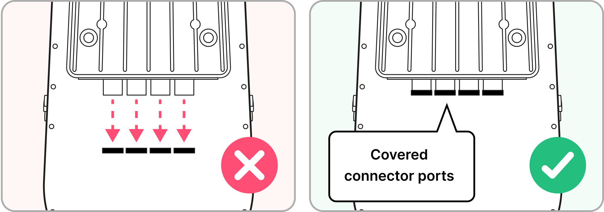
Failure to maintain seals may result in hardware damage or performance degradation, and voided warranty.
Qualified personnel only
Only personnel who have gone through the Taara University training may install the WOC terminals. Training is mandatory for any personnel installing Taara Lightbridge.

Failure to complete online training at Taara University may result in hardware damage, performance degradation, and voided warranty.
2. Prerequisites
Initial setup and health check
Initial setup:
- Perform initial setup and configuration in a controlled environment.
- Update terminal to the latest software and firmware.
Run system health check with Taara Prism:
- Verify no damage from transit or storage.
- If any issues are detected, follow the guidance in Taara Prism and contact support.

If the health check identifies any issues, it will provide guidance about contacting the Taara team for support. Detailed instructions for this can be found at Taara University or reach out to support@taaraconnect.com
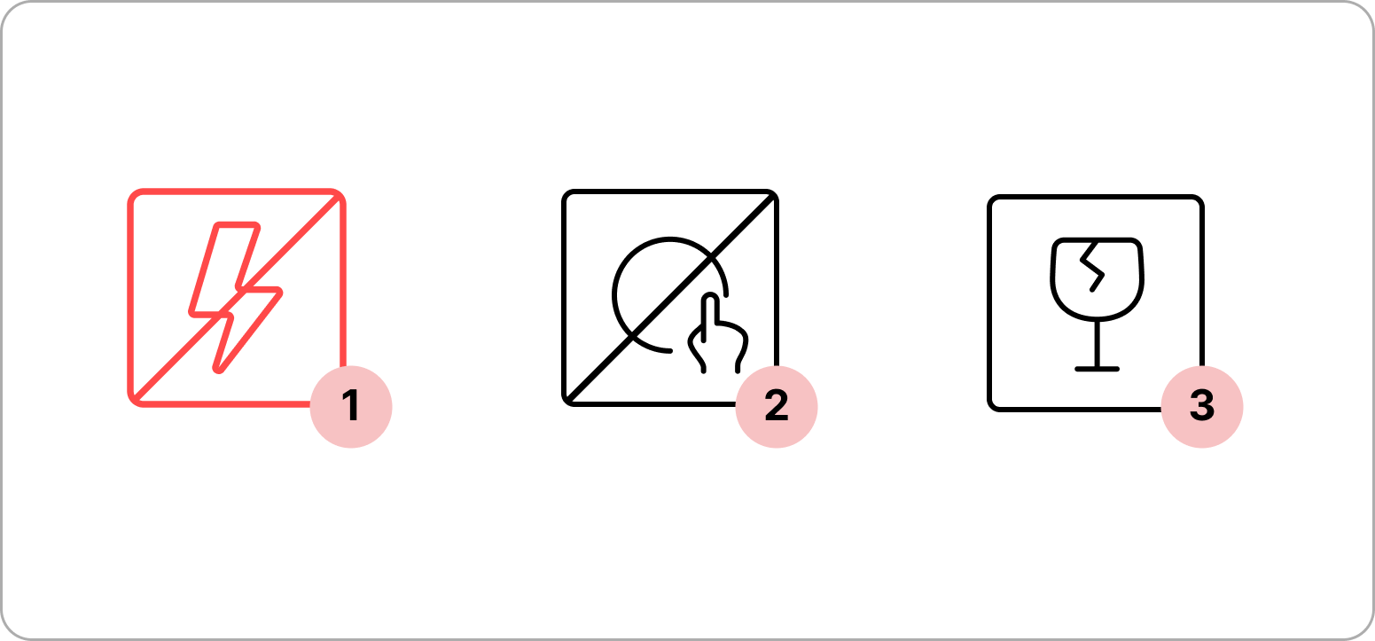
3. Warnings
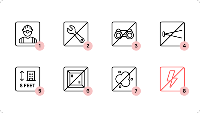
Servicing guidelines
- 1
Qualified personnel only
Only personnel who have gone through the Taara University training may install the WOC terminals.
- 2
No field servicing
WOC terminal cannot be opened or serviced in the field.
Laser safety
- 3
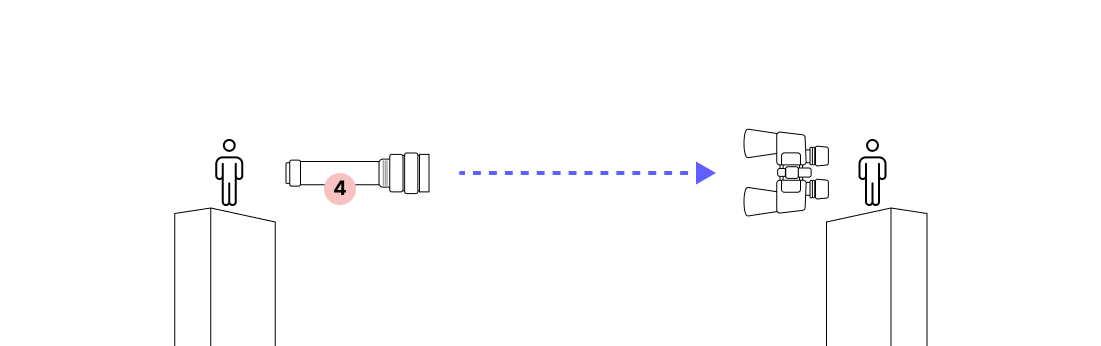
Do not view the beam with aided optics within 5 km
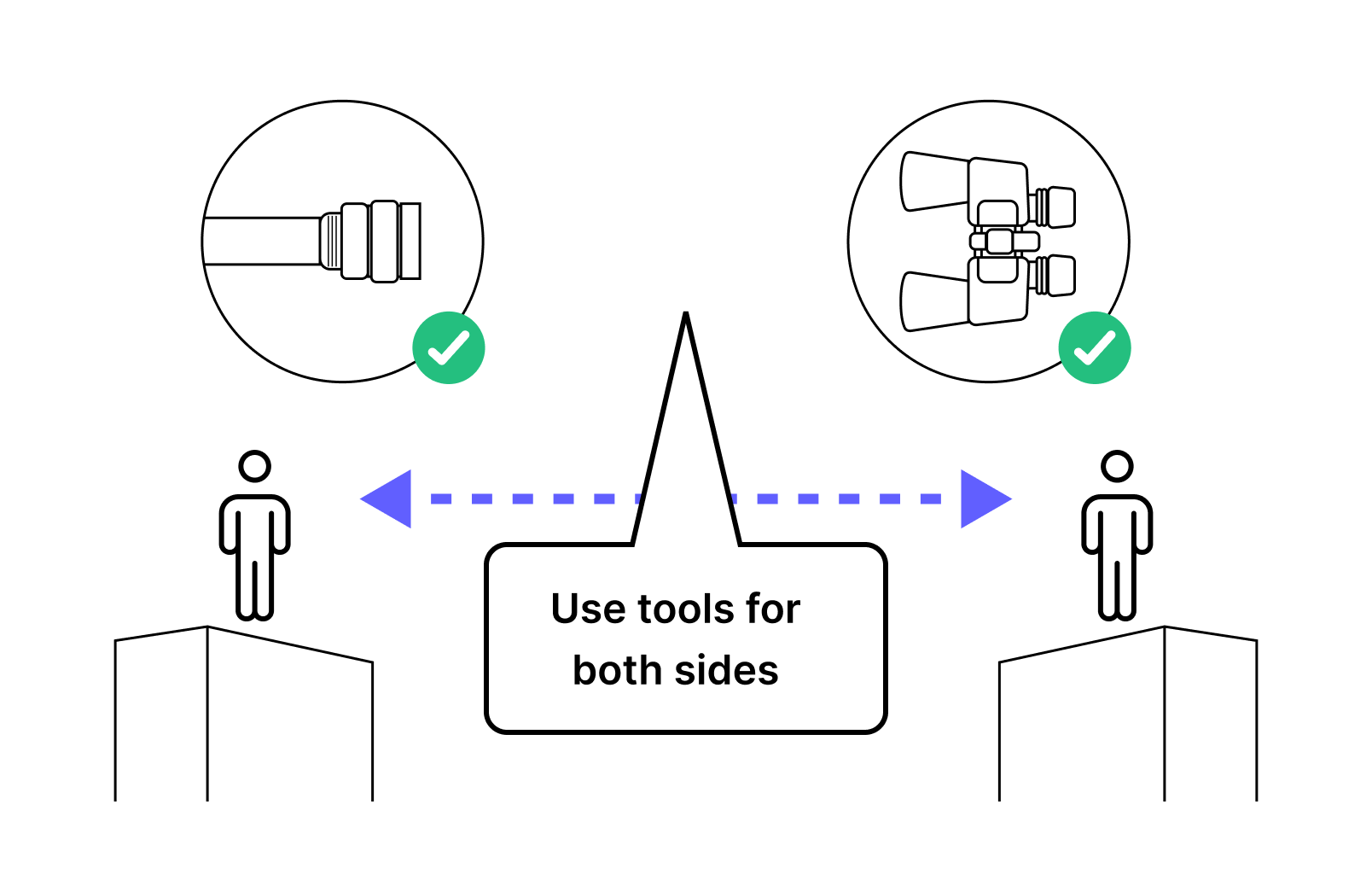
The laser is classified as a point-source Class 1M with a nominal ocular hazard distance of 5 km. Do not view the beam with aided optics (e.g., magnifying glass, binoculars) within this distance.
- 4
Do not look directly into the beam path
The laser is safe to the naked eye. However, as a best practice, do not look directly into the beam path.
Installation guidelines
- 5
Installation height
Terminals should be installed above eye-level, as a best practice.
- 6
No back reflection
Terminals should never be installed facing reflective surfaces (e.g., mirrors, windows).
- 7
Do not remove the dust caps
Do not remove the dust caps from the WOC terminal until you are ready to plug in the Octis connectors.
- 8
Do not power on
Do not power on the WOC terminal until directed.
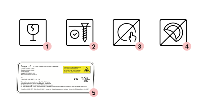
Equipment handling
- 1
Carrying the terminal
The terminal contains delicate optical equipment and must be carried with both hands. When lifted to higher locations, such as a cell tower, it should be placed in a harness bag and lifted carefully to avoid damage.
- 2
Securing fixtures
Ensure all terminals and other equipment installed on a roof are secured in such a way that they cannot be blown away or otherwise affected by wind.
- 3
Do not touch the window beneath the red lens cover
Keep all dust caps and the red lens cover in place until the terminal is mounted and pointed. Avoid touching the window beneath the red lens cover.
- 4 - 5
Do not remove labels
The labels on the terminal describe the regulatory compliance and manufacturing details.
4. Packaging contents
Overview
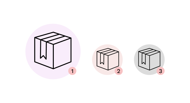
- 1
Main box
- 2
Pole mount box
- 3
Accessory box
Main box
WOC terminal
Pole mount box
Mounting bracket
Accessory box
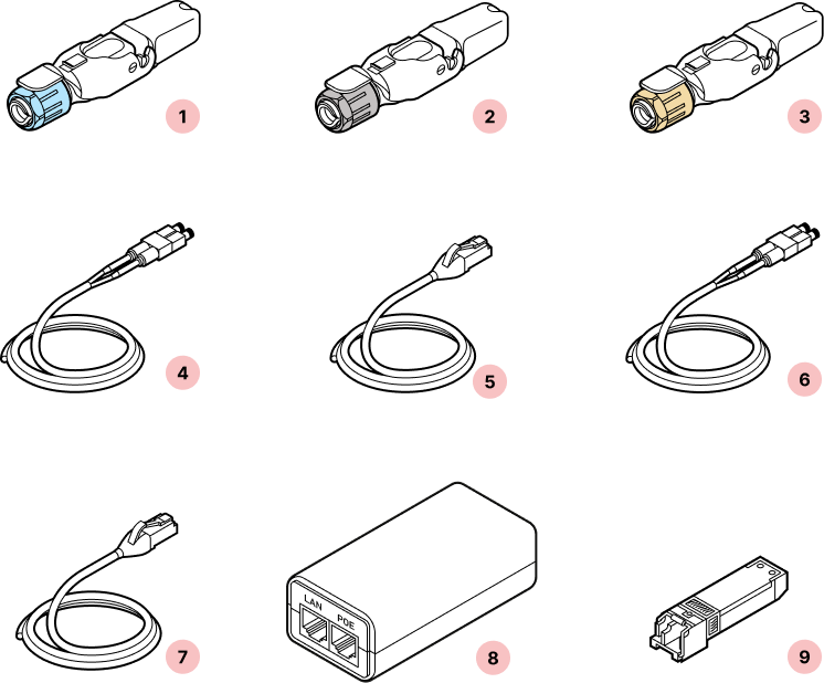
- 1
Octis SFP connector(s)
- 2
Octis RJ45 connector
- 3
Octis DC connector
- 4
Outdoor rated fiber cable (200 feet)
- 5
Outdoor rated CAT6 cable (200 feet)
- 6
Fiber patch cable (3 feet)
- 7
CAT6 patch cable (3 feet)
- 8
PoE Injector with power cable
- 9
SFP+ transceivers x 2
5. Required tools
Site survey toolkit
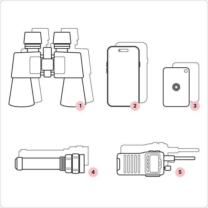
- 1
Binoculars (x2, one for each site)
- 2
Mobile phone with camera (x2)
- 3
Signaling mirror (x2)
- 4
High-powered flashlight (x2)
- 5
Walkie-talkie (if no cell coverage) (x2)
Octis connector assembly toolkit
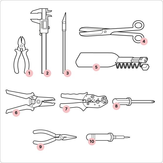
- 1
Wire cutters
- 2
Digital calipers
- 3
X-Acto knife
- 4
Scissors
- 5
LC Fiber cleaner
- 6
Wire strippers
- 7
Wire crimping tool (Radiall OCTI999500)
- 8
Screwdriver
- 9
Pliers* (alternative to Wire crimping tool)
- 10
Soldering iron* (if not using wire crimping tool)
*If pliers are used, solder the wire connections to the crimp contact to ensure a secure and reliable connection.
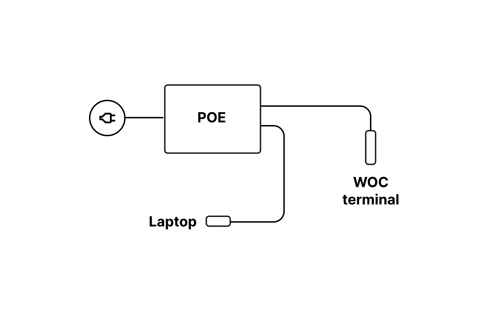
Wireless Optical Communication (WOC) Provisioning
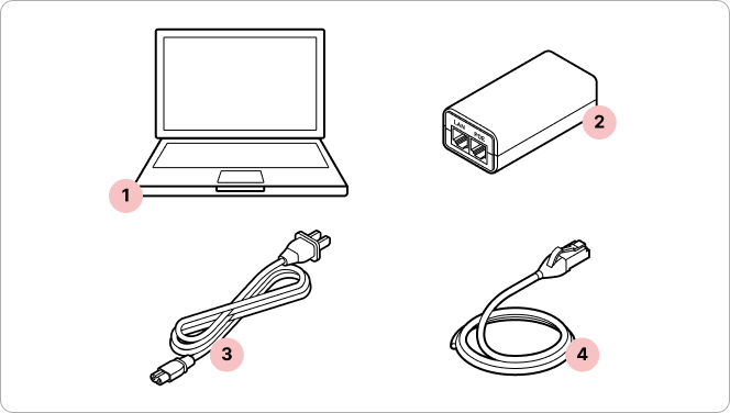
- 1
Laptop
- 2
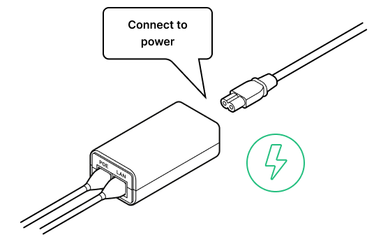
PoE Injector
- 3
Power cord (comes with PoE Injector)
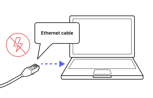
- 4
Ethernet cable
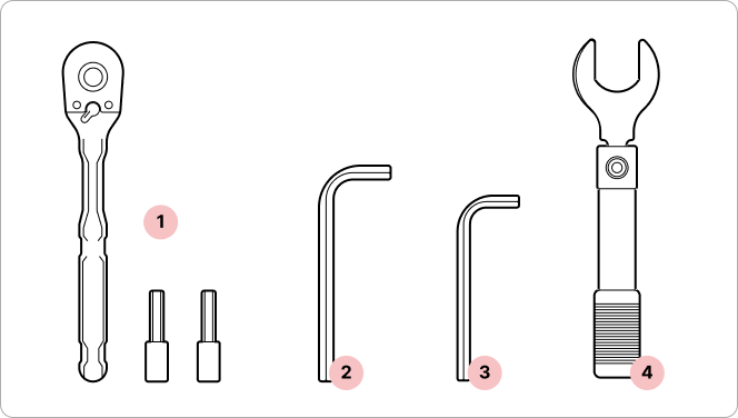
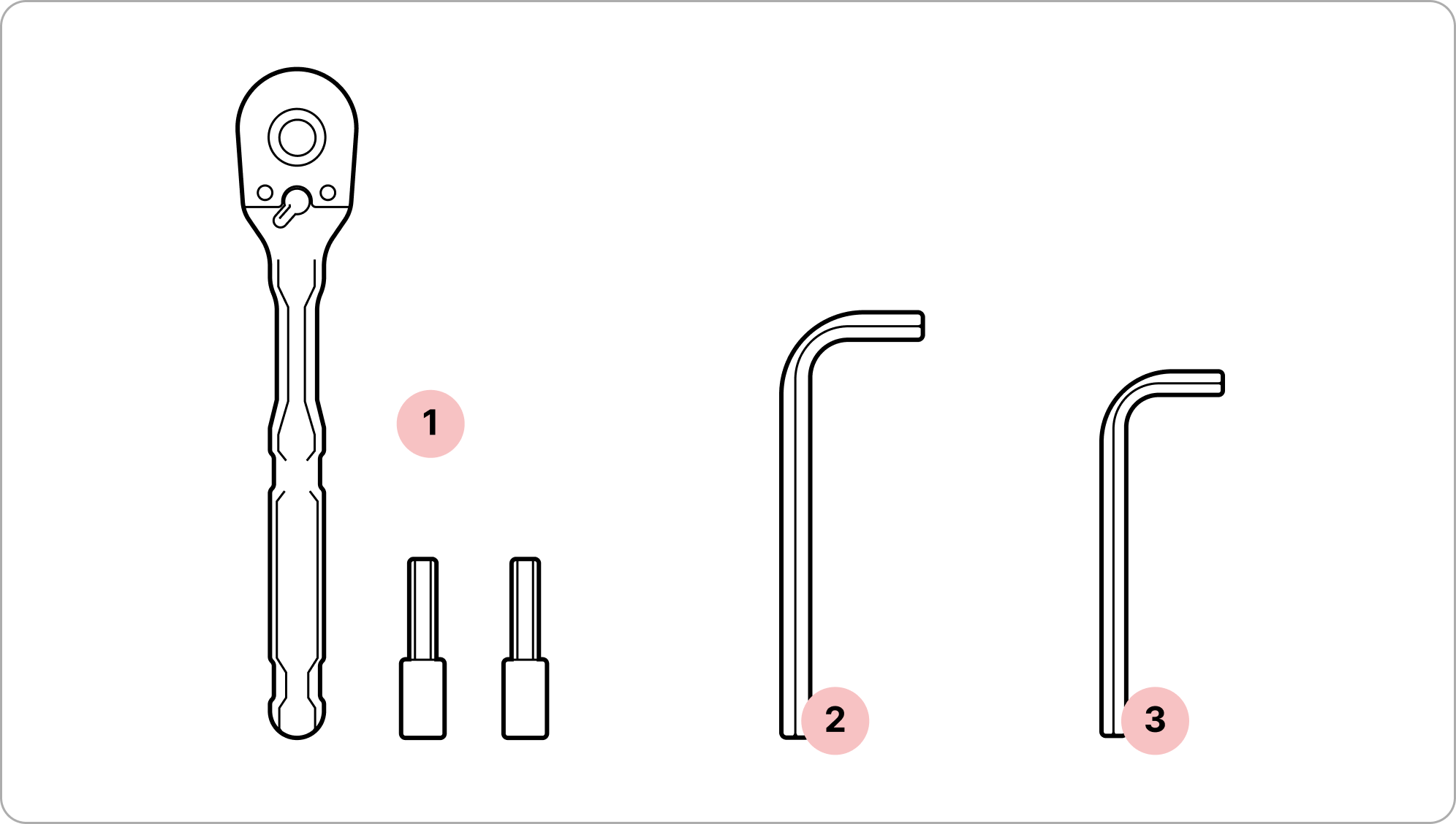
Installation toolkit*
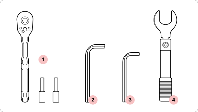
- 1
1/4" ratchet and sockets
- 2
6mm hex key
- 3
5mm hex key
- 4
Torque wrench (not provided)
*These tools will be required at each site.
6. Site survey
Required Tools
- 1
Binoculars (x2, one for each site)
- 2
Mobile phone with camera (x2)
- 3
Signaling mirror (x2)
- 4
High-powered flashlight (x2)
- 5
Walkie-talkie (if no cell coverage) (x2)
*These tools will be required at each site.
Overview
Tips
- Ensure you have reliable means of communication. Use your phone if there's cellular coverage. If there's no coverage, use walkie-talkies to connect with your teammate.
- Communicate with your teammate. Inform your teammate via phone or walkie-talkie about your actions: that you see each other, that you are ready to flash, see the flash, and have documented the flash. Coordinate your actions for the best result.
- Have two sets of gear. Bring binoculars, signaling mirrors, and flashlights to each site so you don't need to transport equipment back and forth.

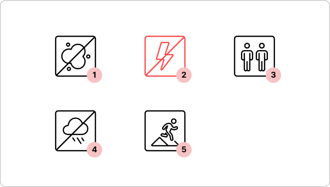
- 1
Avoid working on roofs in the rain to avoid slips.
- 2
Always work in a buddy or team system.
- 3
Installers must be fall-safety compliant.
Register a video recording
Record short videos of the flash on the opposite site, zooming in and out for context. Document all potential obstacles in the beam path, especially trees and power lines.
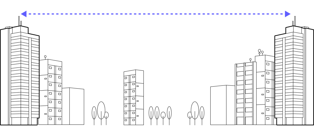
1. Position team members at each site.

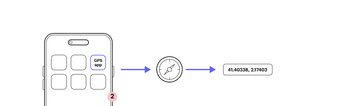
2. Confirm coordinates with GPS.
This will help narrow down the scope of vision for locating the signaling mirror.
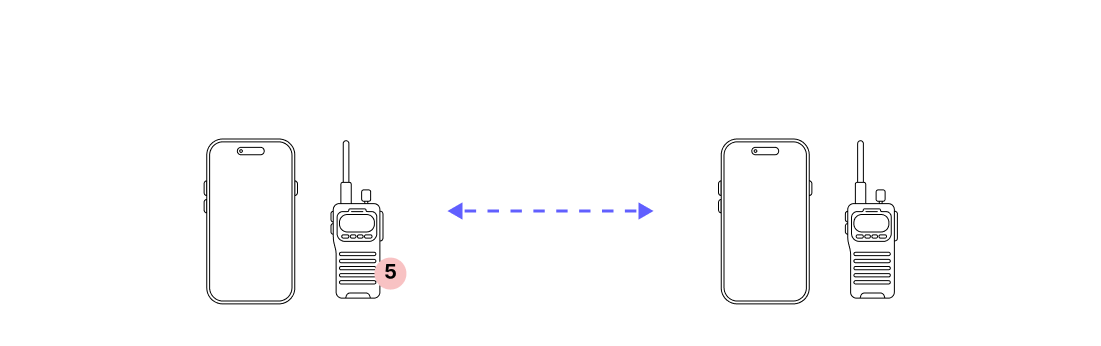
3. Communicate with your teammate via phone or walkie-talkie.
Coordinating a flash pattern with your teammate will help confirm you are viewing each other's flash.
4. If it’s sunny, flash the signal to the other side using a mirror.
Use binoculars to witness the flash for longer distance links.
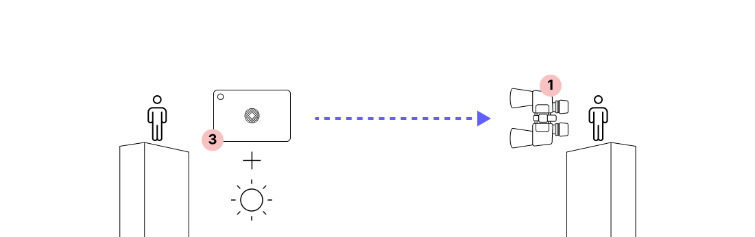
5. If it’s cloudy, flash the signal to the other side using a flashlight.
Use binoculars to witness the flash for longer distance links.
6. Record the signal with a video zoomed in on the far site.
We recommend video over a picture to capture the flash pattern and confirm the other site. This will help you align the terminals when you are bringing up the link.

7. Switch roles and repeat the process (steps 1-6) to confirm alignment from both directions.

7. Site preparation
7.1 Octis RJ45 connector assembly
7.2 Octis DC connector assembly
7.3 Octis SFP connector assembly
7.4 WOC provisioning
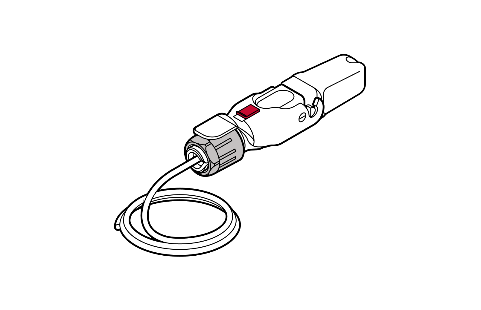
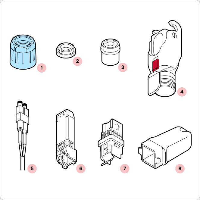
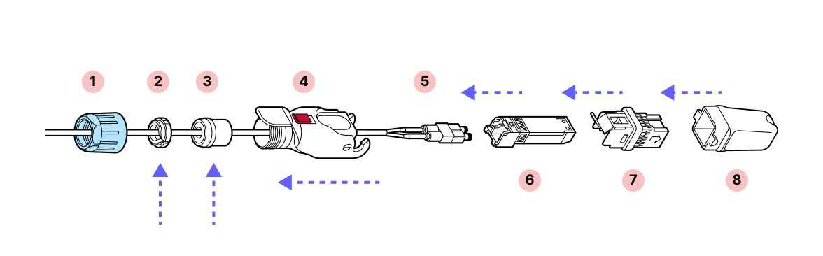
7.1 Octis RJ45 connector assembly
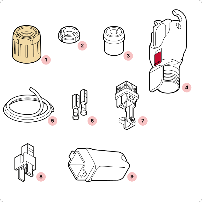
Parts
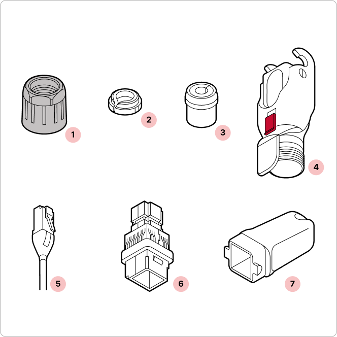
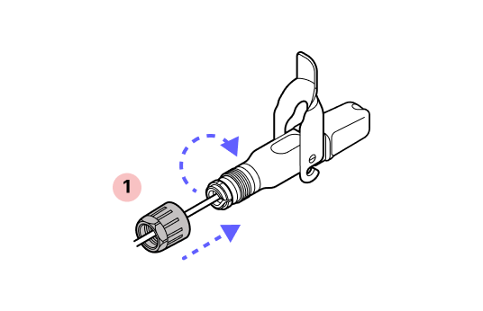
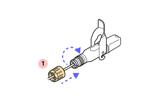
- 1
Black gland nut
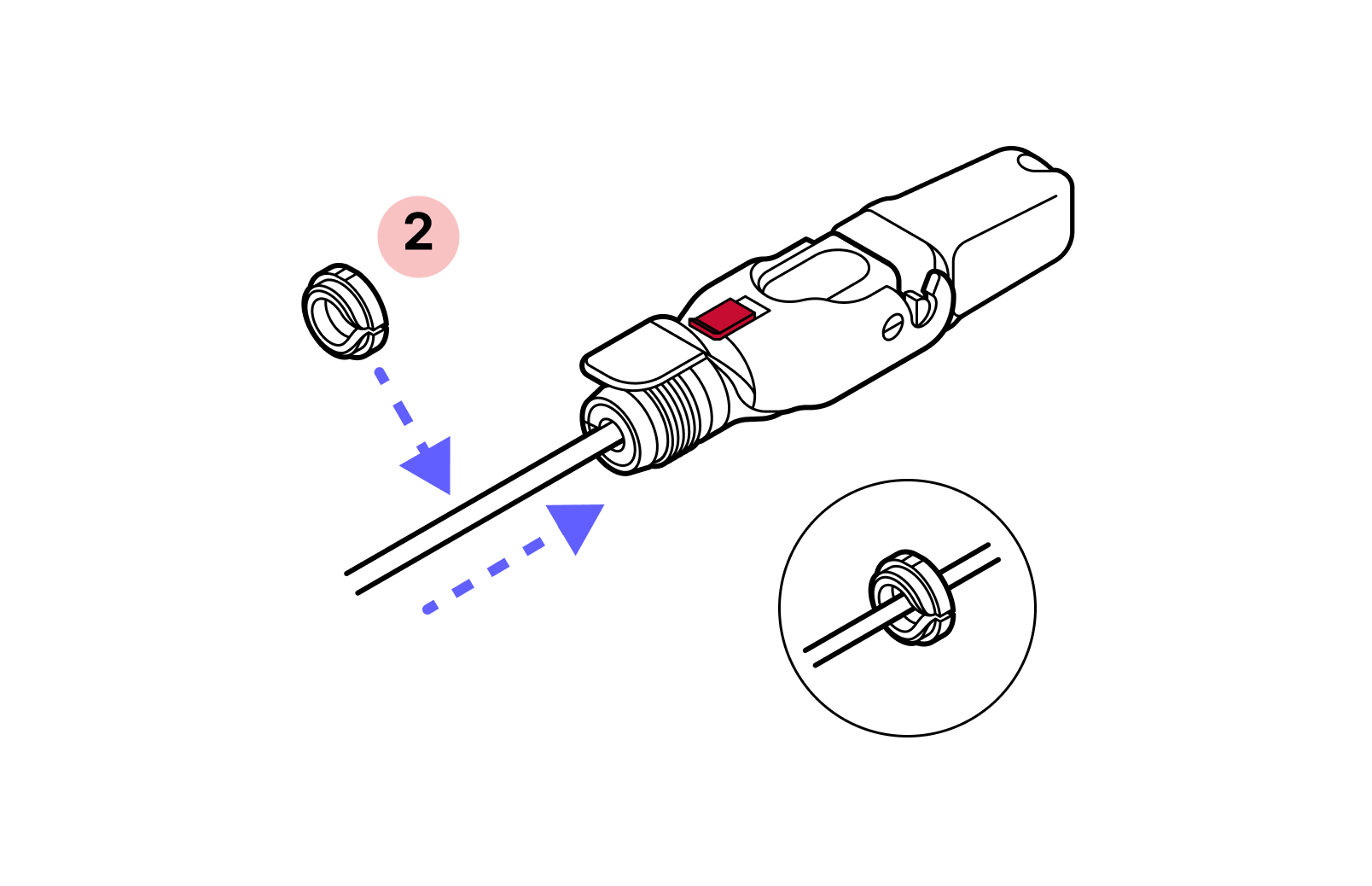
- 2
Tightening cone
- 3
Split rubber gland
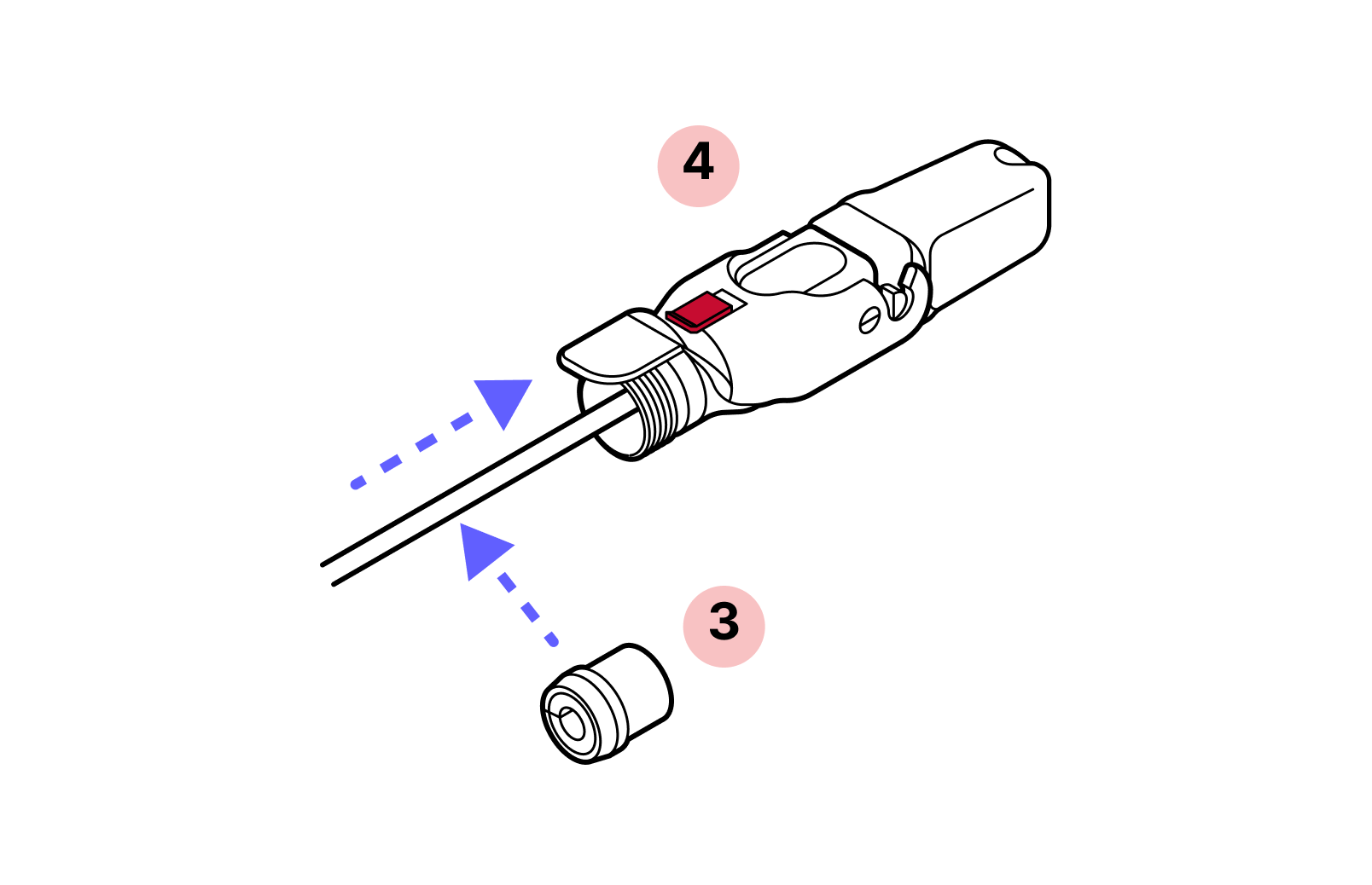
- 4
Housing
- 5
CAT6 patch cable (in accessory box)
- 6
Cable holder
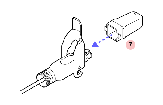
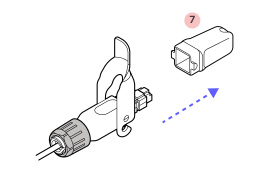
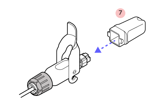
- 7
Plug cap
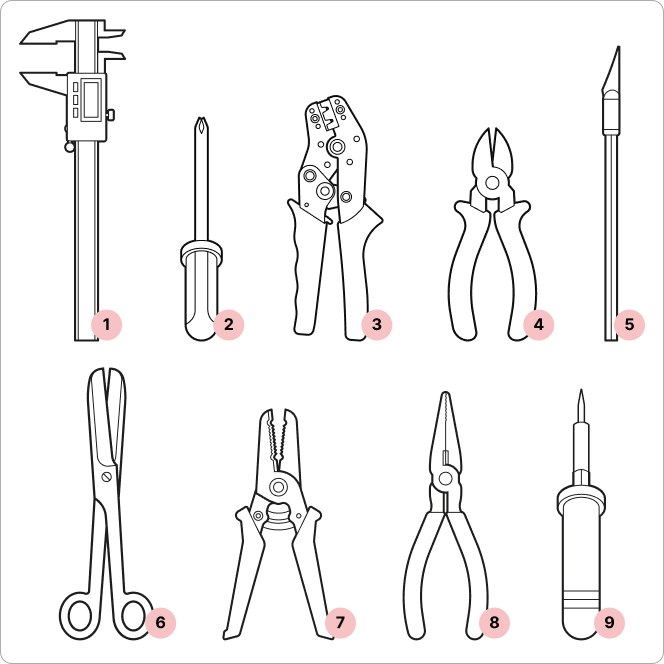
Required tools

Wire cutters
Tips
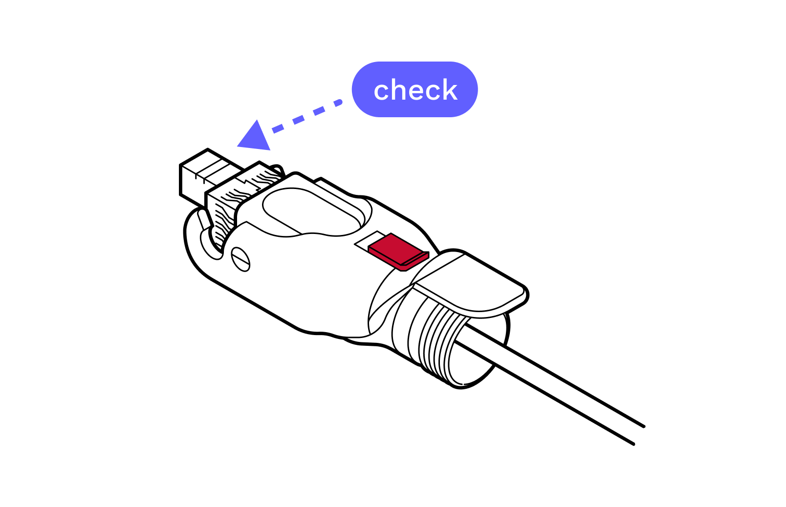
- Check RJ45 depth and nut indication. Double check the RJ45 connector depth using the marking line on the dust cap and make sure the plastic nut is firmly tightened so the cable does not slip. On the Octis cap, use the arrow to verify the length of the visible RJ45 connector (11 millimeters). This is shown in Step 11.
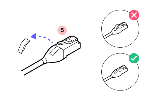
- Modify Ethernet cable. Modify the boot on the Ethernet patch cable: the RJ45 connector must be bare, with no rubber boot, rubber lock tab protector, or other protrusions. Use care to avoid damaging the cable or the Octis RJ45 connector.
- Gently press down to check. To confirm the RJ45 connector is securely locked in place, apply finger pressure.
Important
Do not remove the dust caps from the WOC terminal until you are ready to plug in the Octis connector.
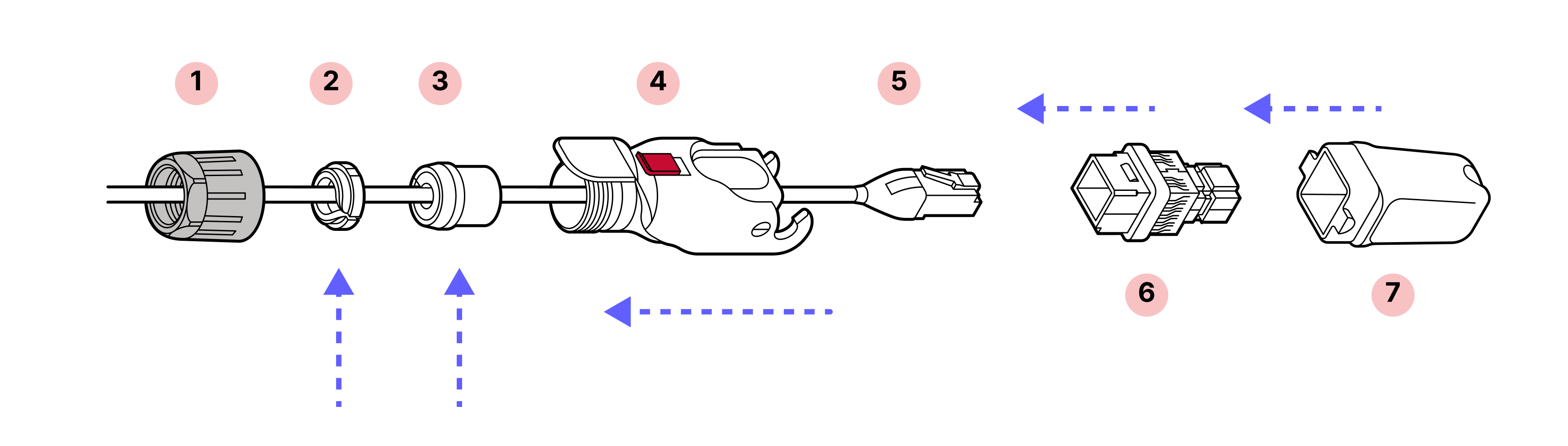
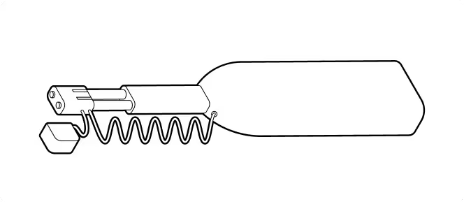
1. The patch cable comes with a boot over the connector. Remove this material.
2. Slide the black gland nut over the cable in the proper orientation.
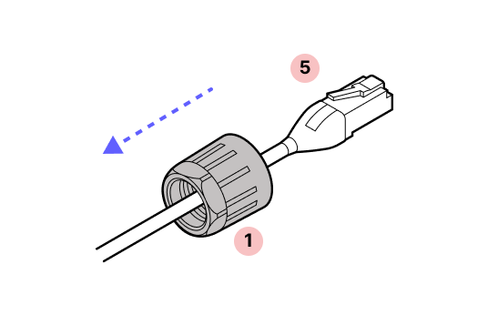
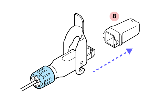
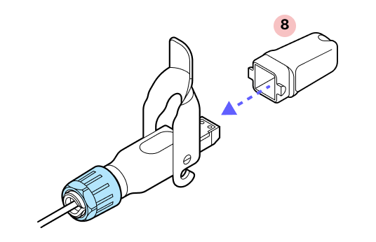
3. With the plastic connector tab facing up on the cable and the red slide lock on top of the housing, slide the housing onto the cable.
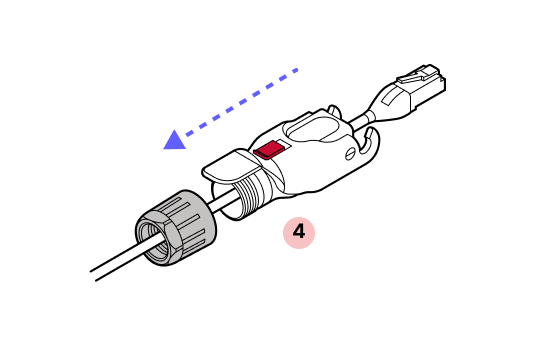
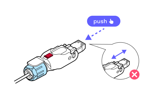
4. IMPORTANT: Push with the cable, not the connector. Push the cable into the metal housing until it clicks into place and is firmly seated.
5. You will hear a click that signals that the cable is fully inserted.
6. Attach the plastic cap and lock the hinge to ensure that everything stays aligned and in place.
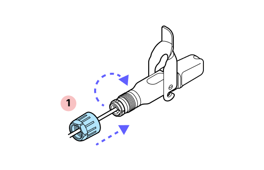
7. Slide the split rubber gland onto the cable in the proper orientation and insert it into the cylindrical part of the Octis housing.
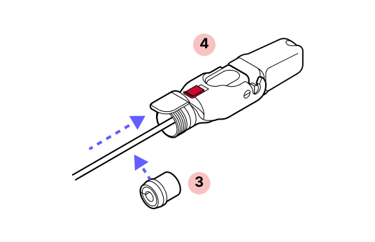
8. Slide the tightening cone onto the cable in the proper orientation.
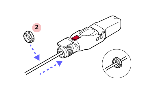
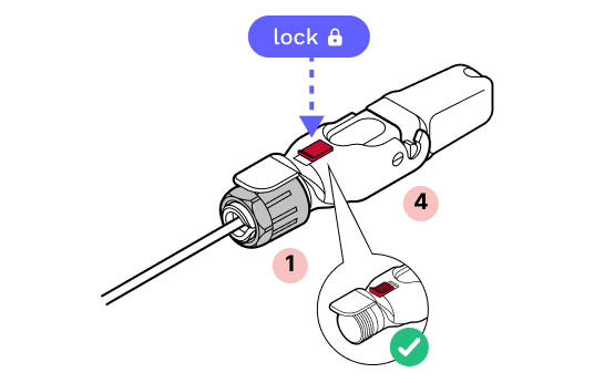
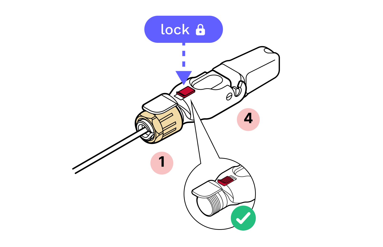
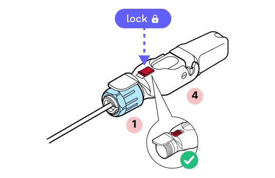
9. Screw the black gland nut into place. IMPORTANT: The gland nut must be tightened so that the red slide lock catches on its edge in the locked position, but not so tight that the hinge cannot fully close without breaking the red lock. DO NOT OVER-TIGHTEN.
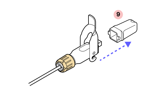
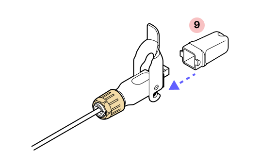
10. Remove the dust cap.
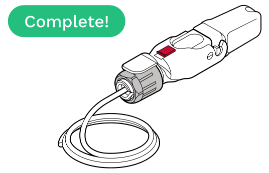
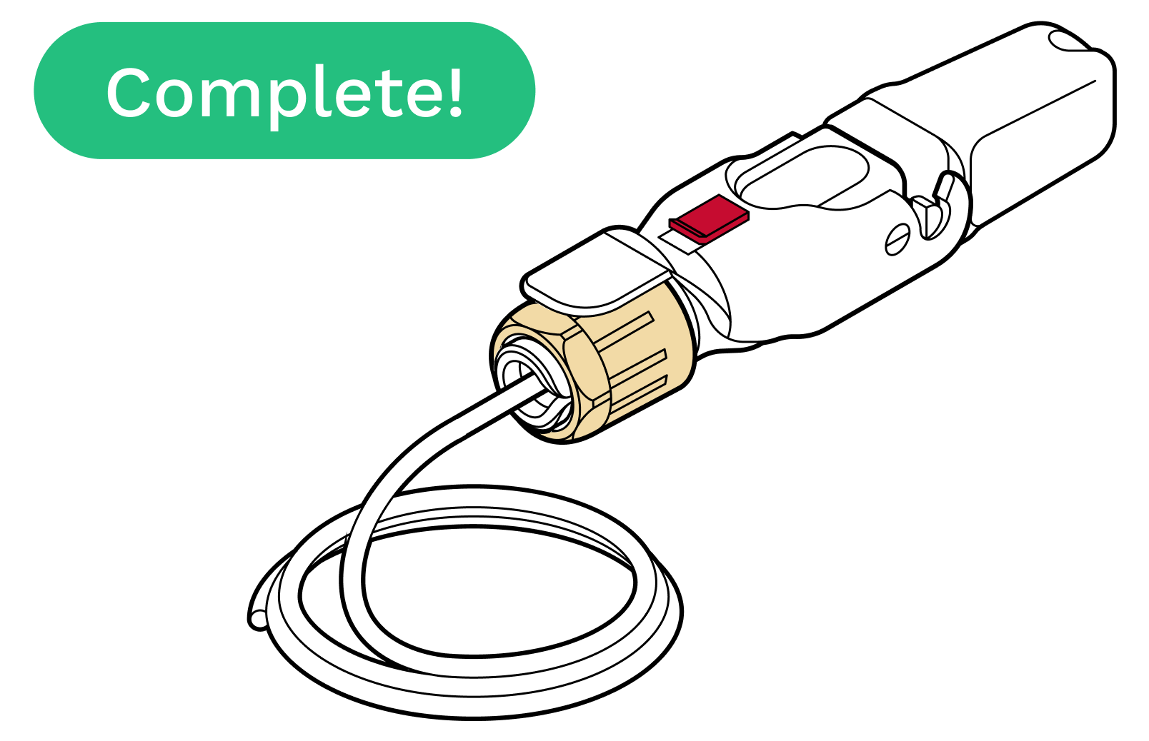
11. Make sure that the connector protrudes the proper distance. The connector should protrude to the flared edges of the cap.
12. Push the connector to ensure it does not slide back. If it does, tighten the black plastic gland nut further.
Incorrect installation may prevent the terminal from powering on.
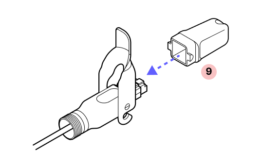
13. Replace the dust cap.
14. Close the red slide lock. IMPORTANT: When closing the hinged lock, the red lock MUST be in the UNLOCKED position. Do not force the hinge lock down or you may break the red slide lock.
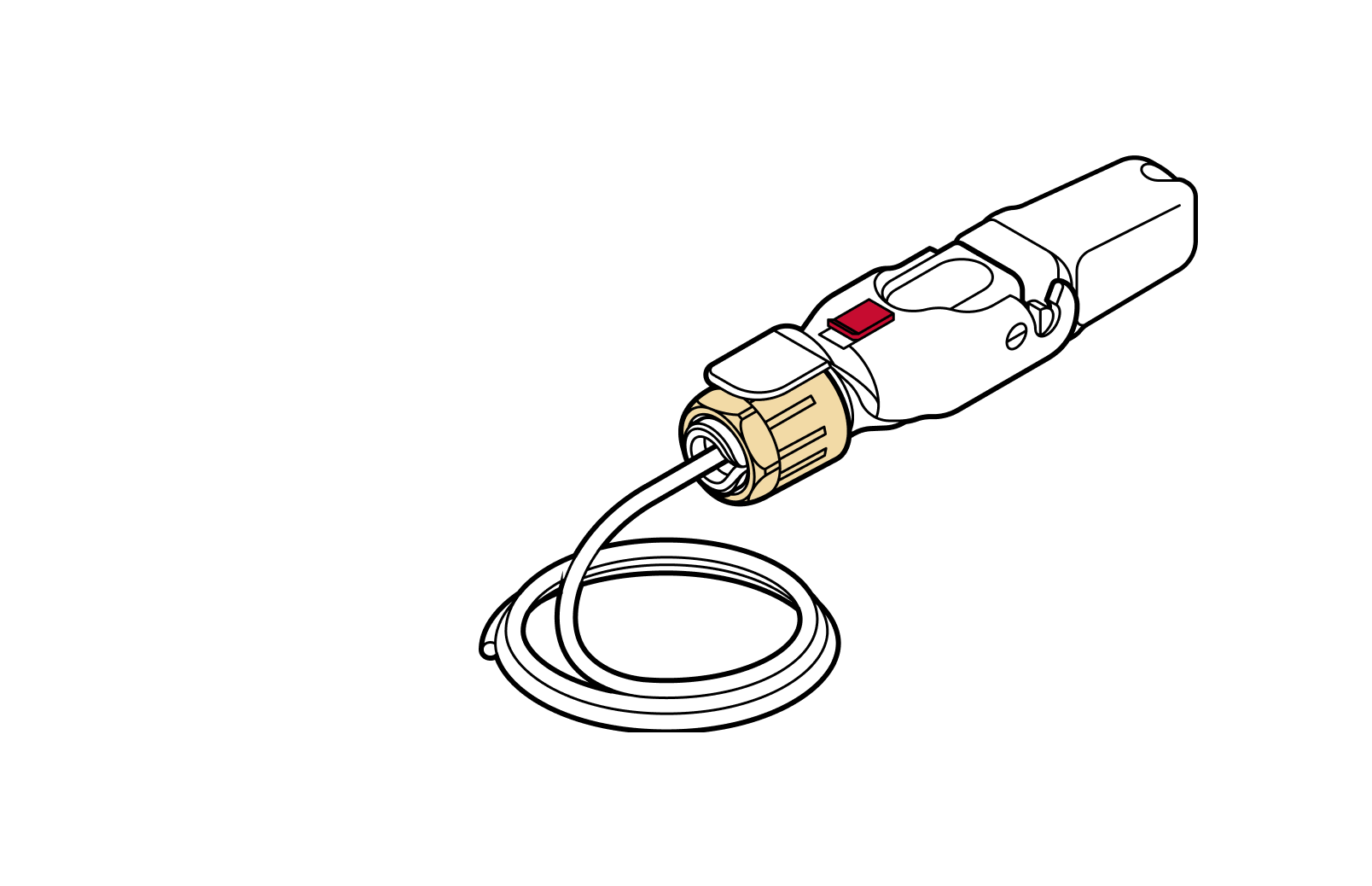
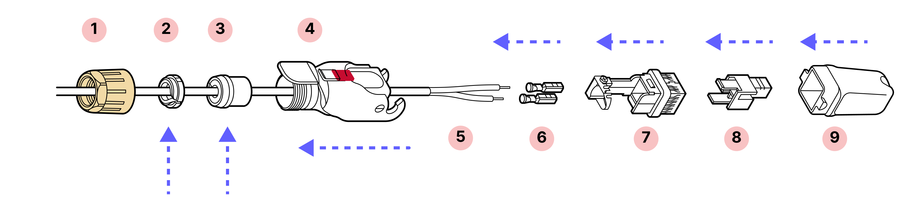
7.2 Octis DC connector assembly
Parts
- 1
Yellow gland nut
- 2
Tightening cone
- 3
Split rubber gland
- 4
Housing
- 5
DC cable (provided by installer)
- 6
Crimp contacts
- 7
Cable holder
- 8
Plastic housing
- 9
Plug cap
Required tools
- 1
Digital calipers
- 2
Screwdriver
- 3
Wire crimping tool (Radiall OCTI999500)
- 4
Wire cutters
- 5
X-Acto knife
- 6
Scissors
- 7
Wire strippers
- 8
Pliers* (if not using crimping tool)
- 9
Soldering iron* (if not using crimping tool)
*If pliers are used, solder the wire connections to the crimp contact to ensure a secure and reliable connection.
Tips
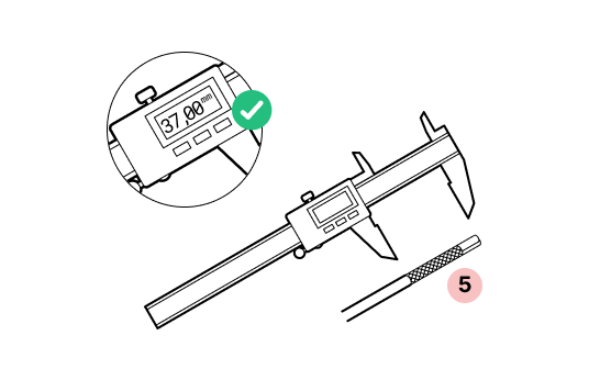
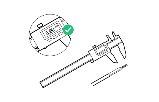
- Be accurate in measurements. Wire stripping is 37mm, conductor stripping is 5mm. Try on the crimp contacts to match.
- Double check the orientation. For this connector, it is very important to observe the correct orientation for the cable holder and plastic housing. Look at the arrow tips on the case and check the instructions twice before attaching the contacts.
Important
Do not remove the dust caps from the WOC terminal until you are ready to plug in the Octis connector.
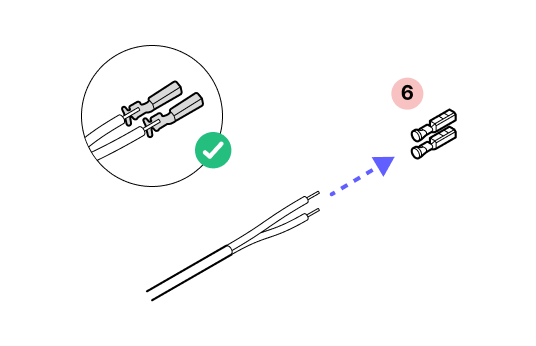
1. Remove 37mm of the outer jacket off the cable. Remove any additional padding material.
2. Strip 5mm of each wire.
3.
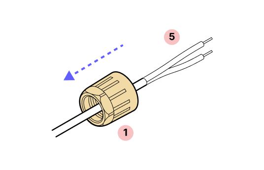
4. Slide the yellow gland nut onto the cable followed by the plastic housing.
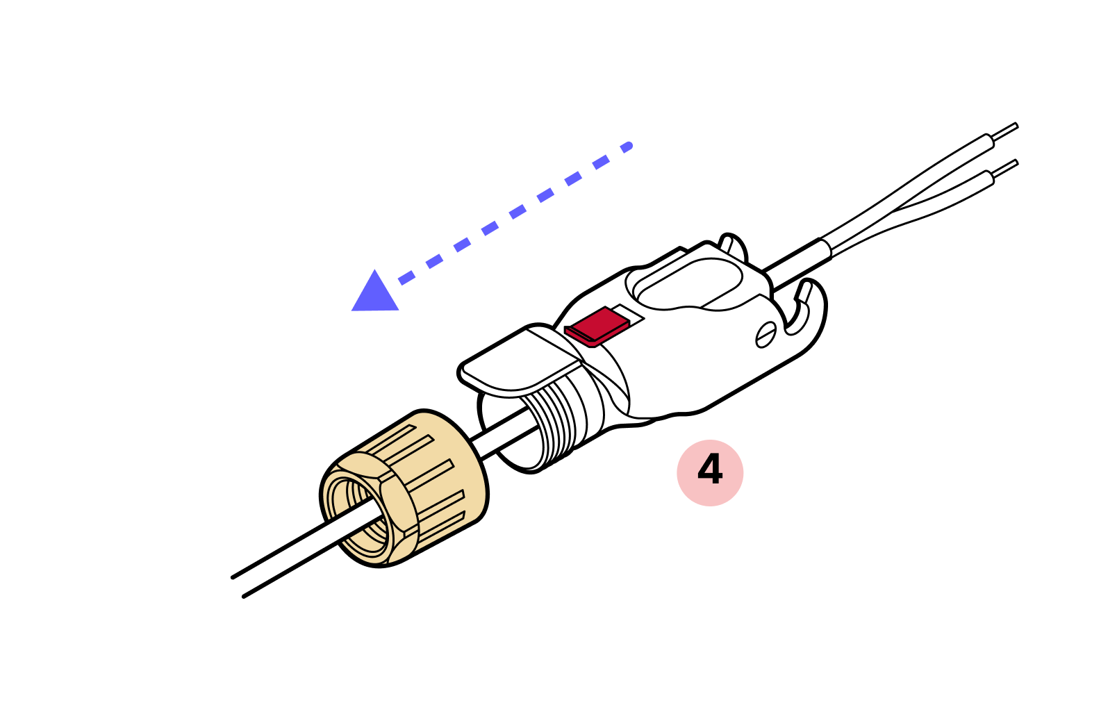
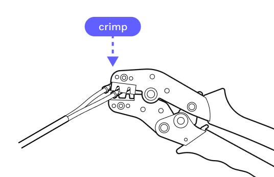
5. Ensure you have selected the proper crimp contact gauge for your wires.
6. If pliers are used, solder the wire connections to the crimp contact to ensure a secure and reliable connection.
7. Back off the screw that holds the metal strap in place and uncurl the strap. Then slide the crimped contacts into and through the housing per the images in steps 8, 9, and 10.

8.
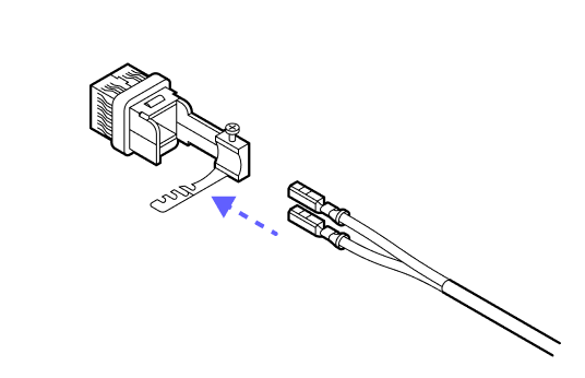
9. With the notch on the top of the crimp contacts and the plastic housing in the orientation shown above, slide the contacts into the housing until they click into place. It does not matter which color goes into which slot.
10.
11. Slide the metal band into place on the screw and tighten. There is a nut visible through a window in the side of the housing. Tighten the screw until the nut is snug at the top.
12. Line up the arrow on the outer housing with the arrow on the inner housing and slide them together until they click.
13. Slide the dust cap onto the Octis connector.
14. Slide the split rubber gland onto the cable and fit it snugly into the cylindrical portion of the Octis housing.
15. Slide the tightening cone onto the cable and make sure it is in the proper orientation.
16. Open the hinge lock and tighten the yellow gland nut. Note that the red slide lock locks on the rim of this nut so it must be tightened enough to catch the red slide lock when in the locked position. DO NOT OVER-TIGHTEN.
17. IMPORTANT: When closing the hinged lock, the red lock MUST be in the UNLOCKED position. Do not force the hinge lock down or you may break the red slide lock.
18. Check to make sure the housing or connectors don't push back into the housing before replacing the dust cap.
19.
20.
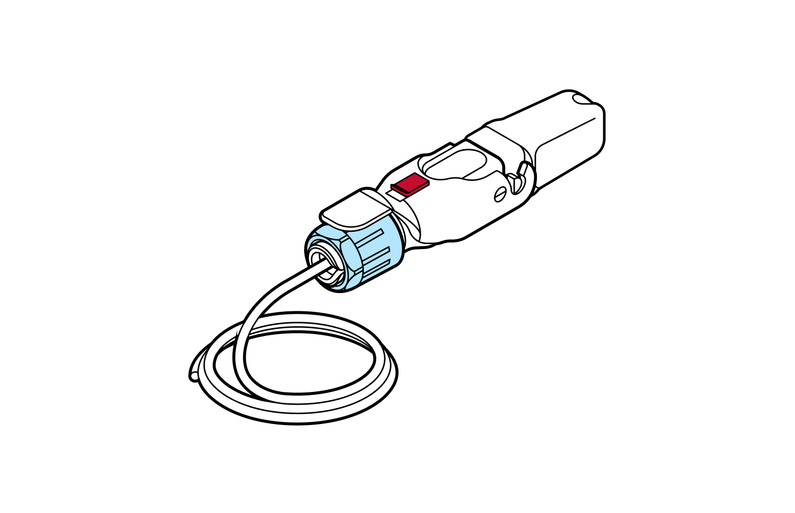
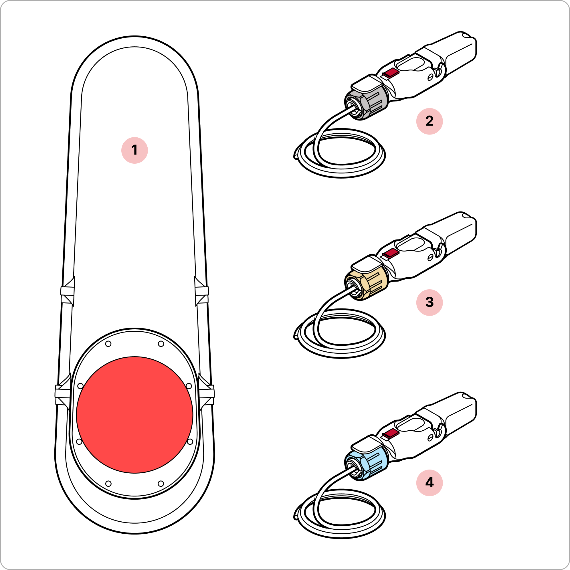
7.3 Octis SFP connector assembly
Parts
- 1
Blue gland nut
- 2
Tightening cone
- 3
Split rubber gland
- 4
Housing
- 5
Fiber optic cable
- 6
SFP Module
- 7
SFP Module holder
- 8
Plug cap
Required tools
LC Fiber cleaner
Tips
- Ensure proper fiber cable handling. Good practice involves careful handling and management of the fiber assembly. Use a plug to protect the cable from dust. Use of a fiber cleaning tool before connecting is highly recommended.
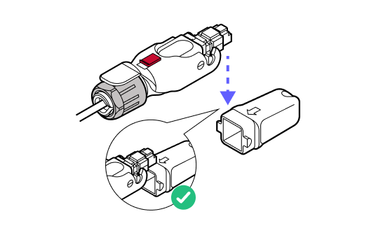
- Listen for the 'clicks'. As you assemble the components, make sure to listen for the distinctive 'click' sounds, which indicate that the parts are securely connected. These clicks provide an auditory confirmation that the assembly is properly sealed.
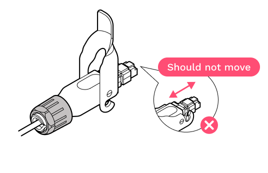
- Gently press down to check. Verify the SFP is locked in place by applying finger pressure.
Important
Do not remove the dust caps from the WOC terminal until you are ready to plug in the Octis connector.
1. Make sure that the dust caps are on the connector and remain on until the connector is ready to be cleaned and plugged in.
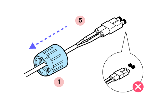
2. Slide the blue nut and the outer Octis housing over the cable.
3. Remove the dust cap and clean the fiber connectors. DO NOT touch the fiber connectors with your fingers.
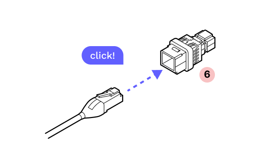
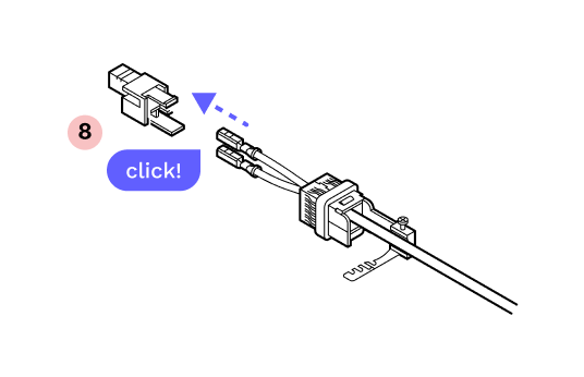
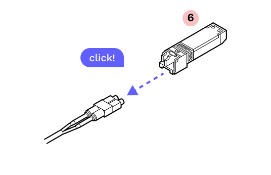
4. Plug the connector into the SFP until you hear a click.
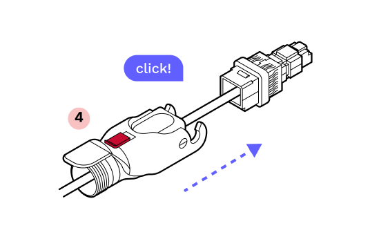
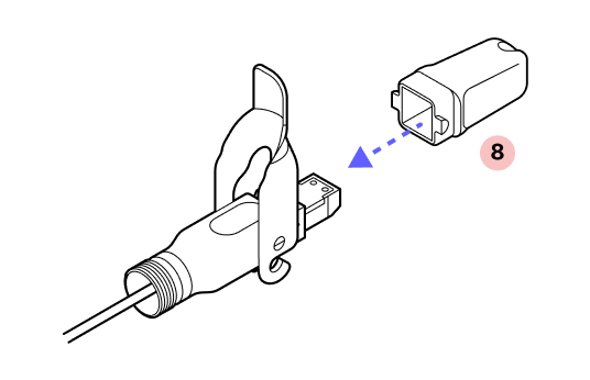
5. With the metal tab on top in-line with the tab on the fiber assembly, gently insert the assembly into the inner housing until it clicks into place.
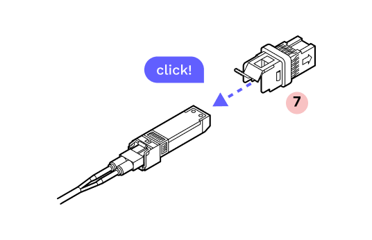
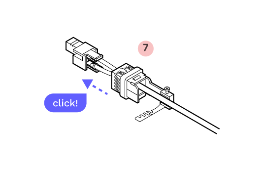
6. With the arrows on the corners of the outer and inner housing lining up, slide the plastic housing onto the metal housing until you hear a click.
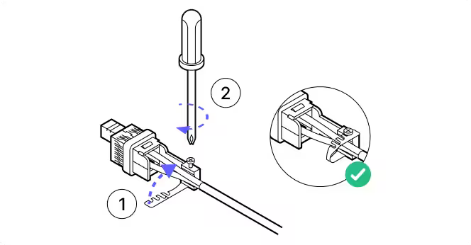
7. Attach the plastic cap and lock the hinge to ensure that everything stays aligned and in place.
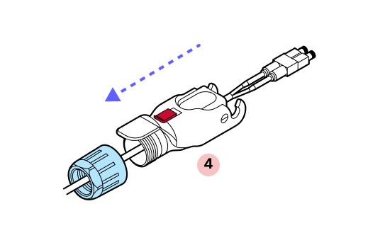
8. Slide the split rubber gland onto the cable in the proper orientation and into the cylindrical portion of the Octis housing. If the cable has label bands, slide them down so they are not pushed into the Octis housing.
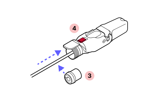
9. Slide the tightening cone over the cable in the proper orientation.
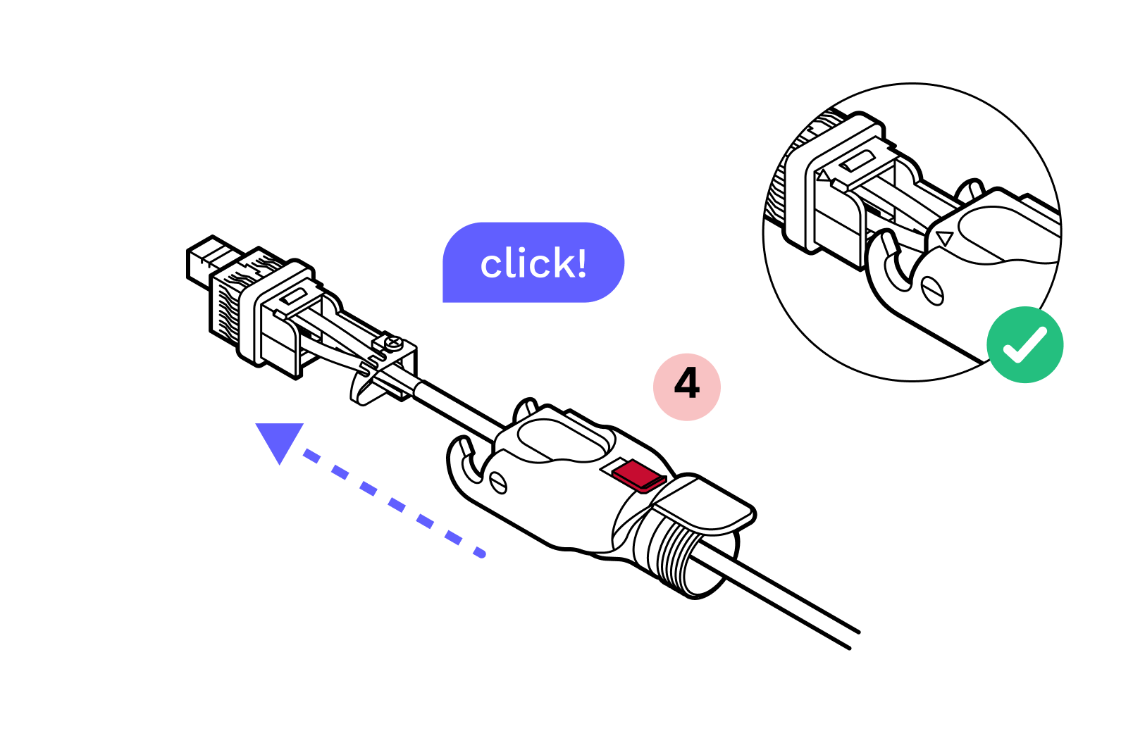
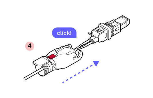
10. Screw the blue gland nut into place. IMPORTANT: The gland nut must be tightened so that the red slide lock catches on its edge when in the locked position. DO NOT OVER-TIGHTEN.
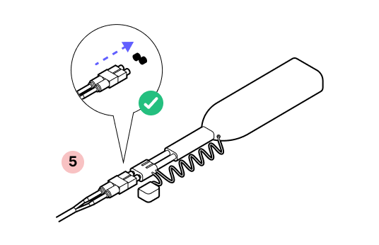
11. Remove the dust cap.
12. Press gently on the SFP ensuring that it does not slide into the connector body. If it does, this means the metal housing was not pressed on until it clicked. Disassemble and begin again from Step 5.
13. Replace the dust cap.
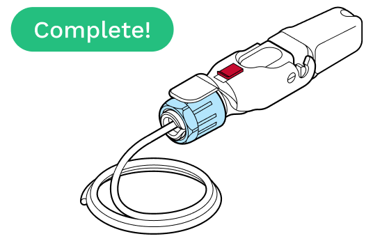
14. Lock the red slide lock. IMPORTANT: When closing the hinged lock, the red lock MUST be in the UNLOCKED position. Do not force the hinge lock down or you may break the red slide lock.
[object Object]
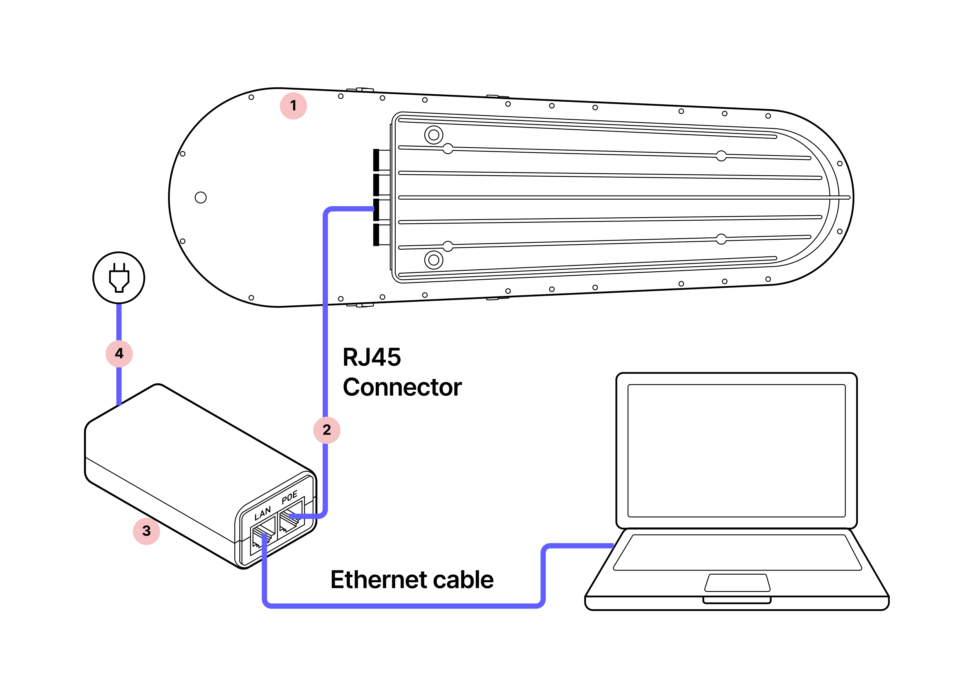
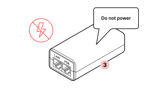
7.4 WOC provisioning
Parts
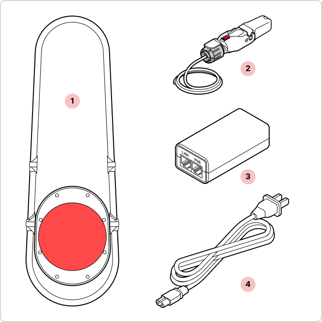
- 1
WOC terminal
- 2
RJ45 pigtail
- 3
PoE injector
- 4
Power cord*
*The power cord is required for powering the PoE injector during the provisioning process.
Required tools
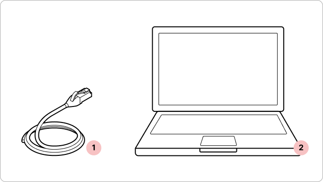
- 1
Standard ethernet cable (not provided)
- 2
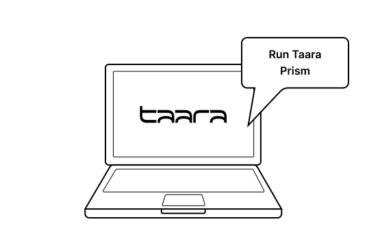
Laptop with Taara Prism
Tips
- Pre-install the app. Install Taara Prism on the management computer. Download the latest version of Taara Prism from the Taara Partner Portal. To successfully complete the link provisioning, Taara Prism needs to be connected to the internet.
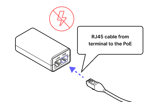
- Connect the power last. Verify the POE injector is unpowered when inserting the Octis RJ45 connector.
- Prepare a second Ethernet patch cable. A second Ethernet patch cable will be required for the provisioning process (not included in the WOC accessory box).
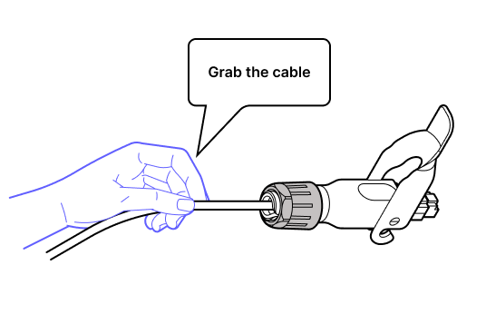
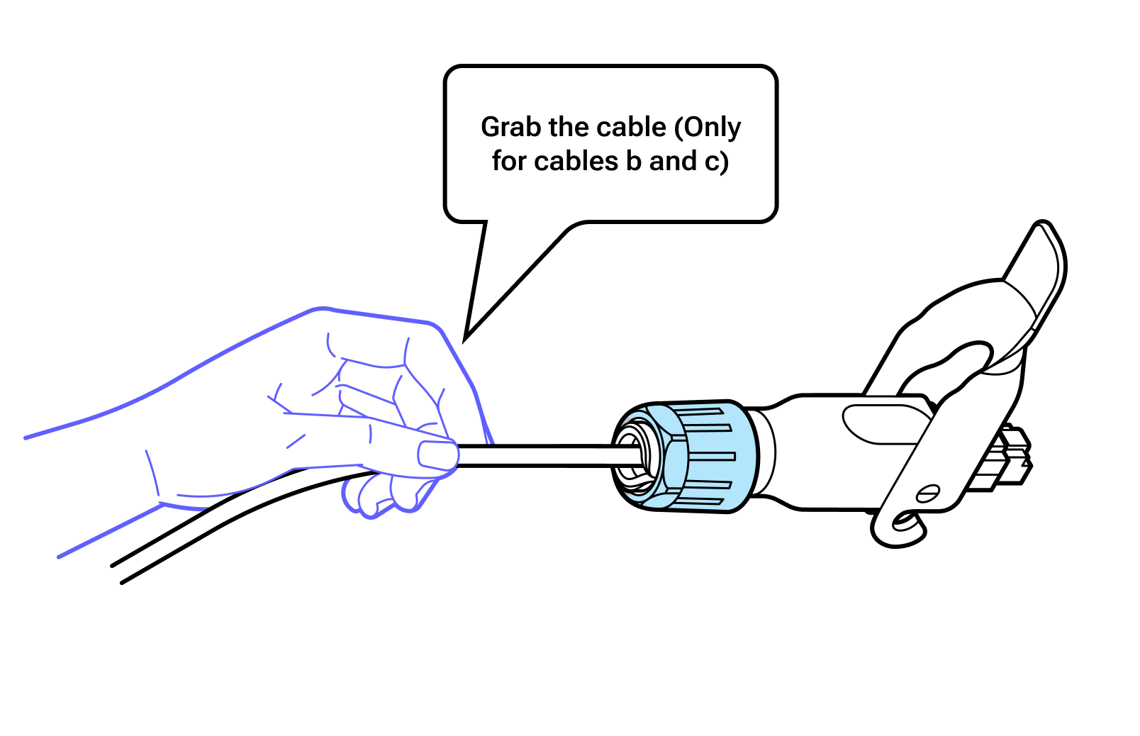
- Grab the cable, not the connector. Insert the RJ45 Octis connector into the WOC terminal by pushing on the cable instead of using the connector body.
- 1
Do not power the WOC terminal on until directed.
- 2
Avoid touching the window beneath the red lens cover.
- 3
Carrying the terminal. The terminal contains delicate optical equipment and must be carried with both hands.
Important
Do not remove the dust caps from the WOC terminal until you are ready to plug in the Octis connector.
1.
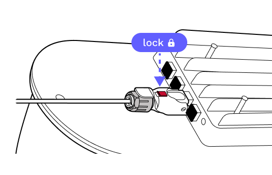
2. While pushing with the cable, not the connector, plug the RJ45 connector into the terminal and lock it into place.
3.
4. Plug the other end of the ethernet cable into the PoE injector.
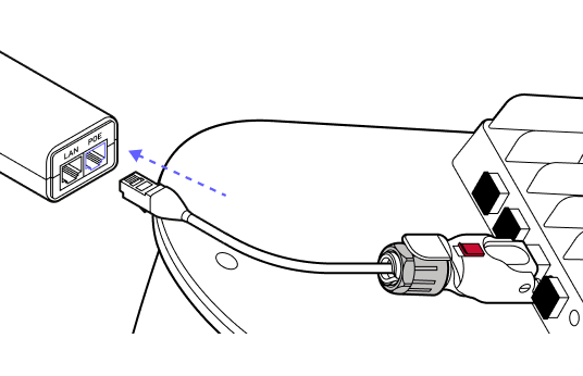
Grab the cable
5.
6. Use an ethernet cable to connect the PoE injector to the LAN port on the laptop.
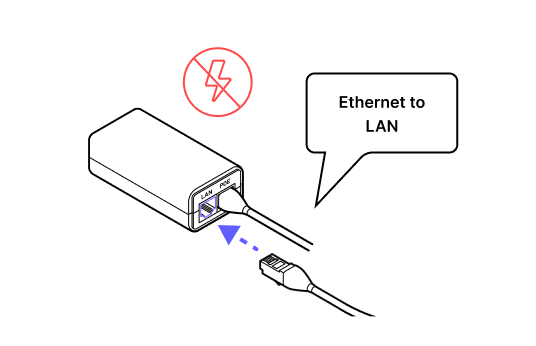
7. DO NOT POWER the terminal until directed.
8.
9. Download Taara Prism from the Taara Partner Portal at partner.taaraconnect.com and connect the terminal to run a software check prior to taking the unit out into the field. Once the user is prompted to begin the provisioning process the software check is complete.

8. Physical installation
8.1 Installing the mounting bracket
8.2 Installing the WOC terminal
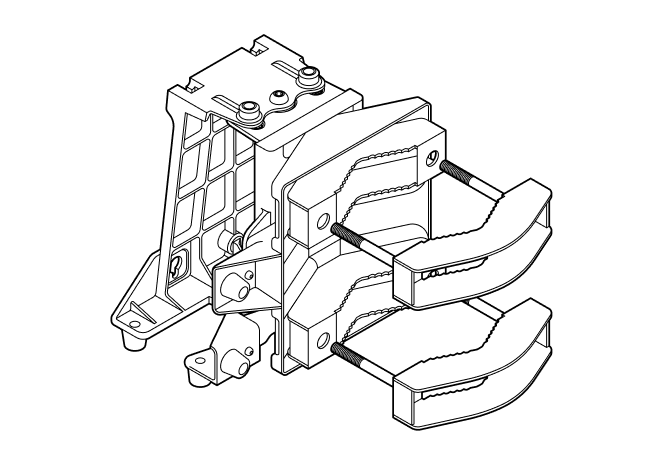
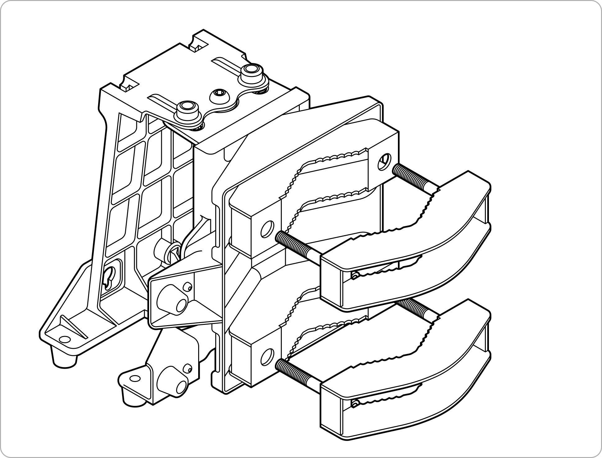
8.1 Installing the mounting bracket
Parts
Mounting bracket
Site survey toolkit
- 1
Binoculars (x2, one for each site)
- 2
Mobile phone with camera (x2)
- 3
Signaling mirror (x2)
- 4
High-powered flashlight (x2)
- 5
Walkie-talkie (if no cell coverage) (x2)
Installation toolkit
- 1
1/4" ratchet and sockets
- 2
6 mm hex key
- 3
5 mm hex key
- 4
Torque wrench (not provided)
Tips
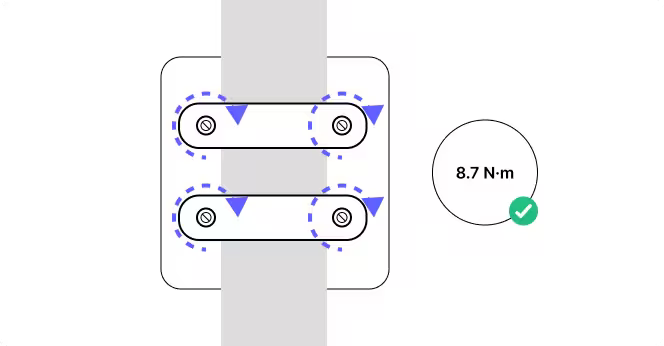
- Verify the six azimuth and elevation bolts. Verify that the six azimuth and elevation locking bolts are loose and mid-travel before coarse pointing the mounting bracket.
- Torque control. Ensure all fasteners are tightened to the specified torque 8.7 Newton meters (N-m) max to secure the mounting bracket in place.
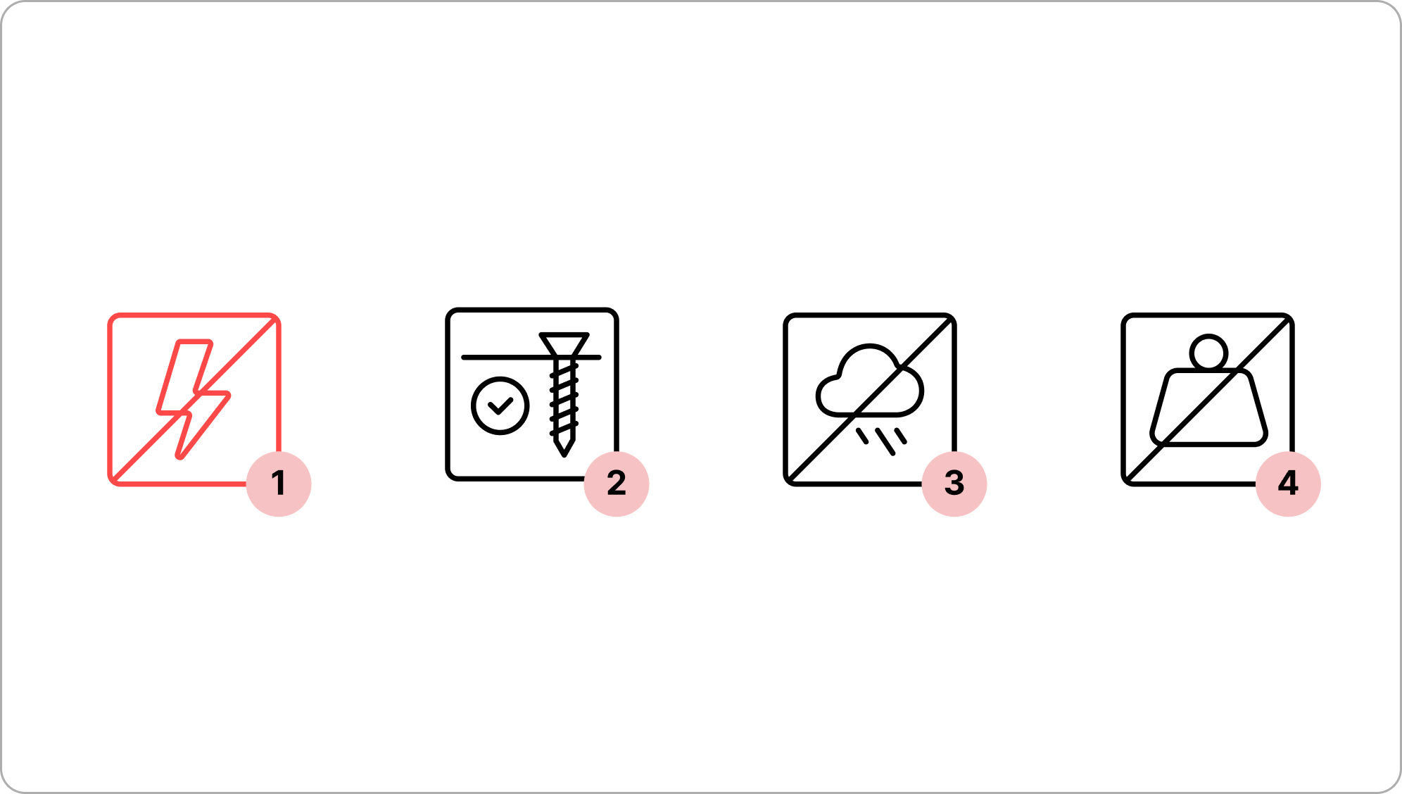
- Electrical safety. If the equipment is connected to a power source, ensure it is de-energized before installation to avoid electric shock.
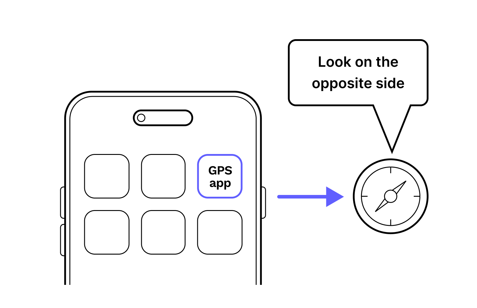
- GPS App. Use your GPS app and communicate with your teammate to verify each other's position.
- 1
Do not remove the dust caps from the WOC terminal until you are ready to plug in the Octis connectors.
- 2
Do not power on the terminal before completing this step.
- 3
It is recommended to perform the installation with a partner.
- 4
Avoid working in strong winds or unfavorable weather conditions.
- 5
Use safety harnesses when working on elevated areas.Avoid working in strong winds or unfavorable weather conditions.
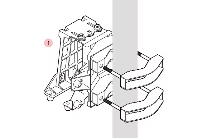
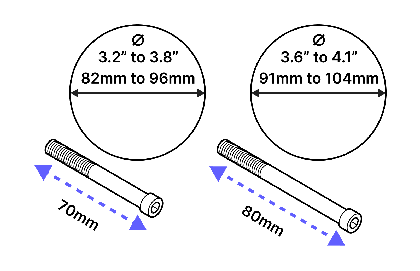
1. The bracket comes with two bolt sizes to fit different pole diameters. Select the appropriate bolt size for your installation.
2. Pre-install the bolts on one of the bracket jaws.
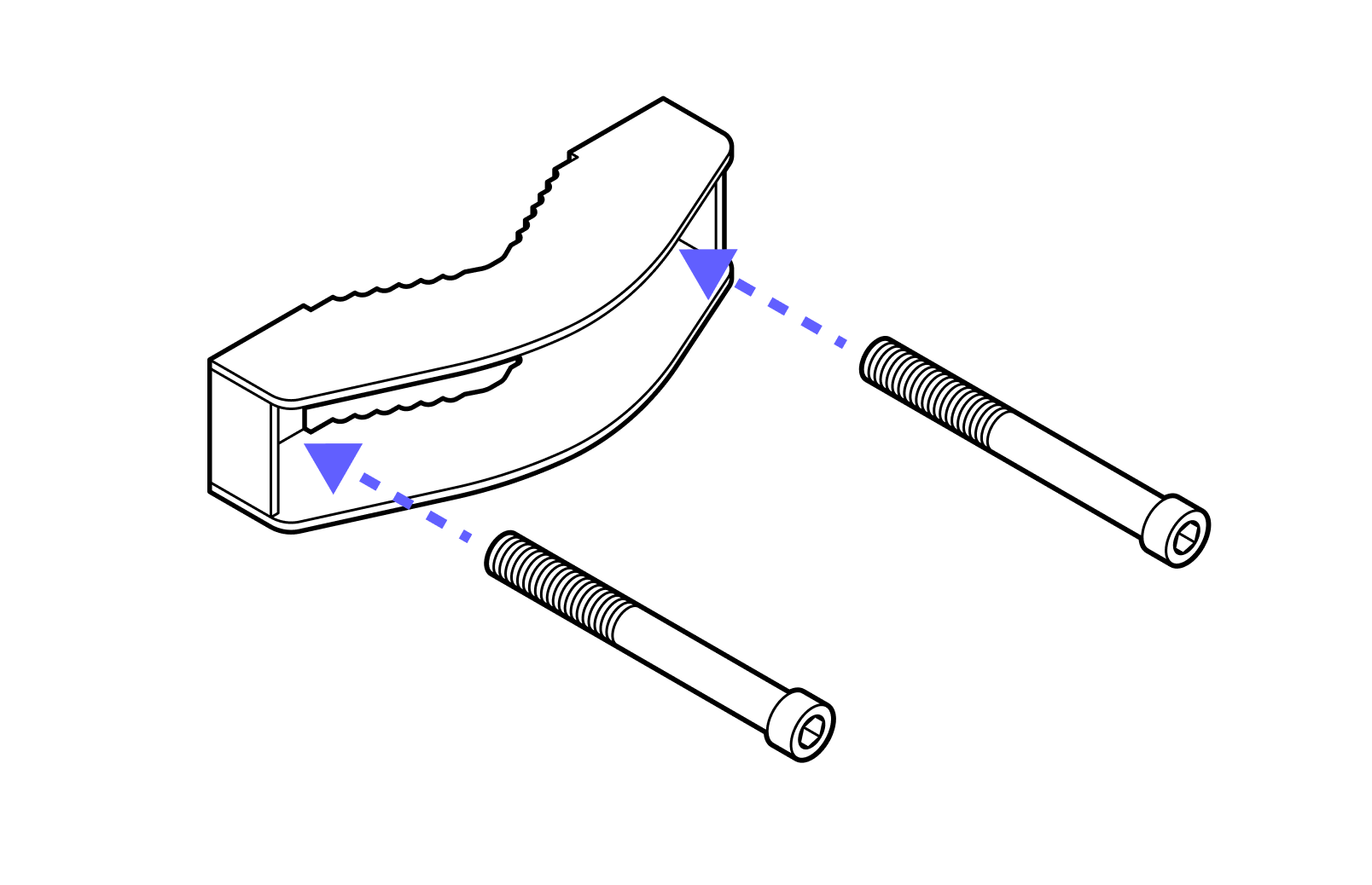
3. Repeat for the second jaw.
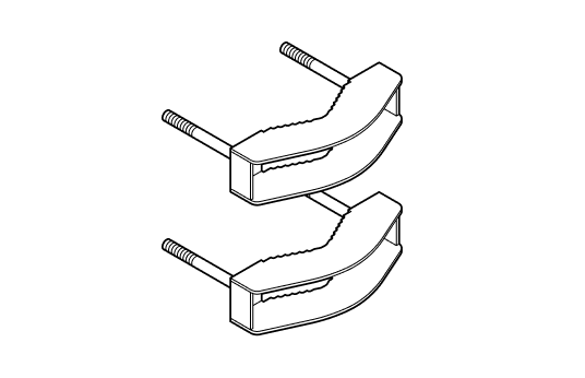
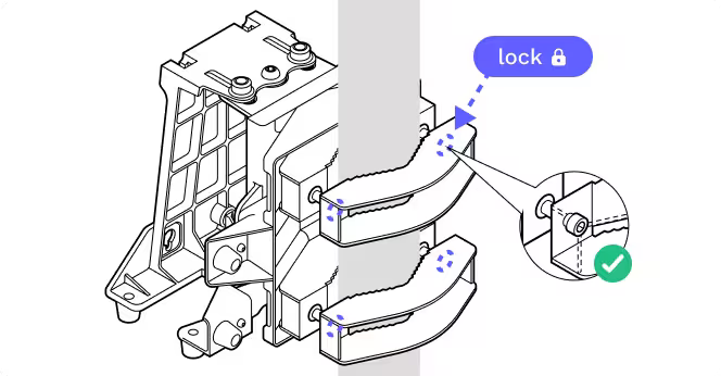
4. Fasten the jaws to the bracket around the pole. Note the orientation of the bracket - the wide end of the bracket should be on the bottom.
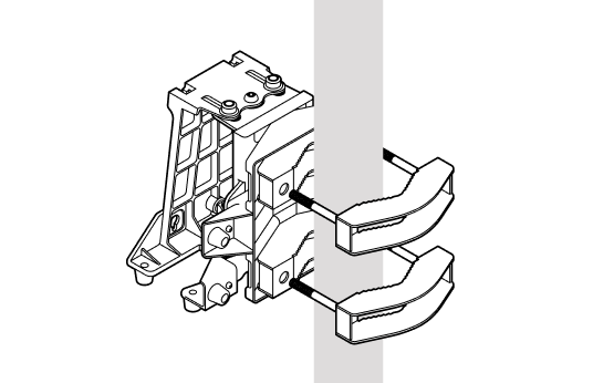
5. Tighten the bolts enough to hold the bracket in place. DO NOT FULLY TIGHTEN as you may need to make adjustments to the bracket's alignment.
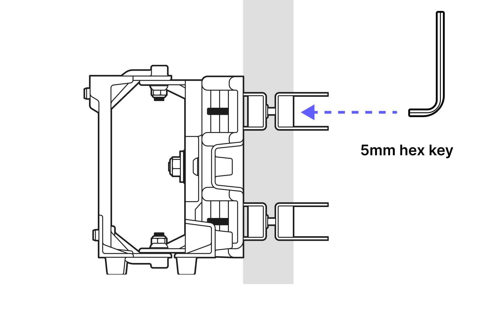
6. The azimuth and elevation adjustment fasteners are set to mid-travel.
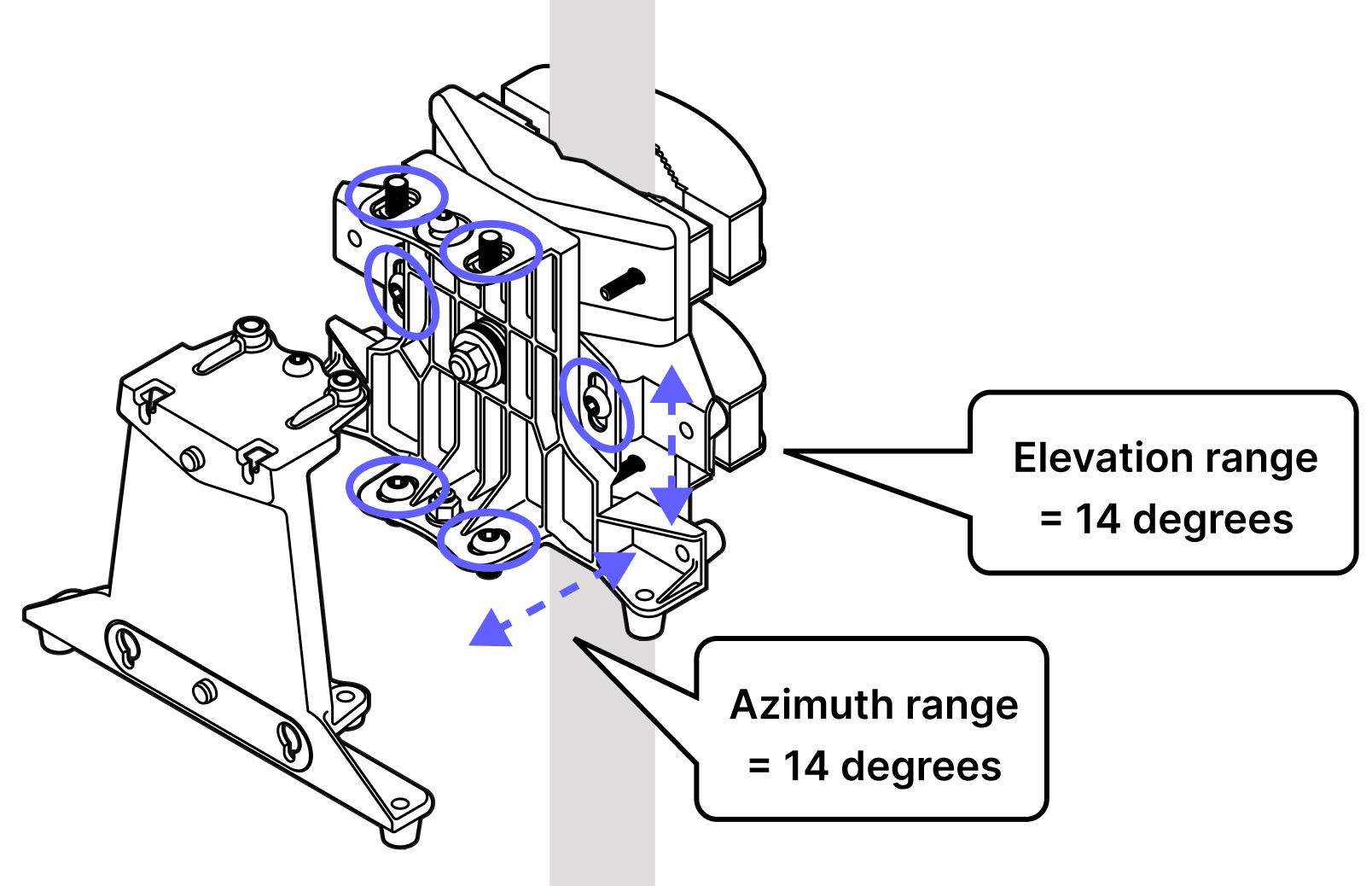
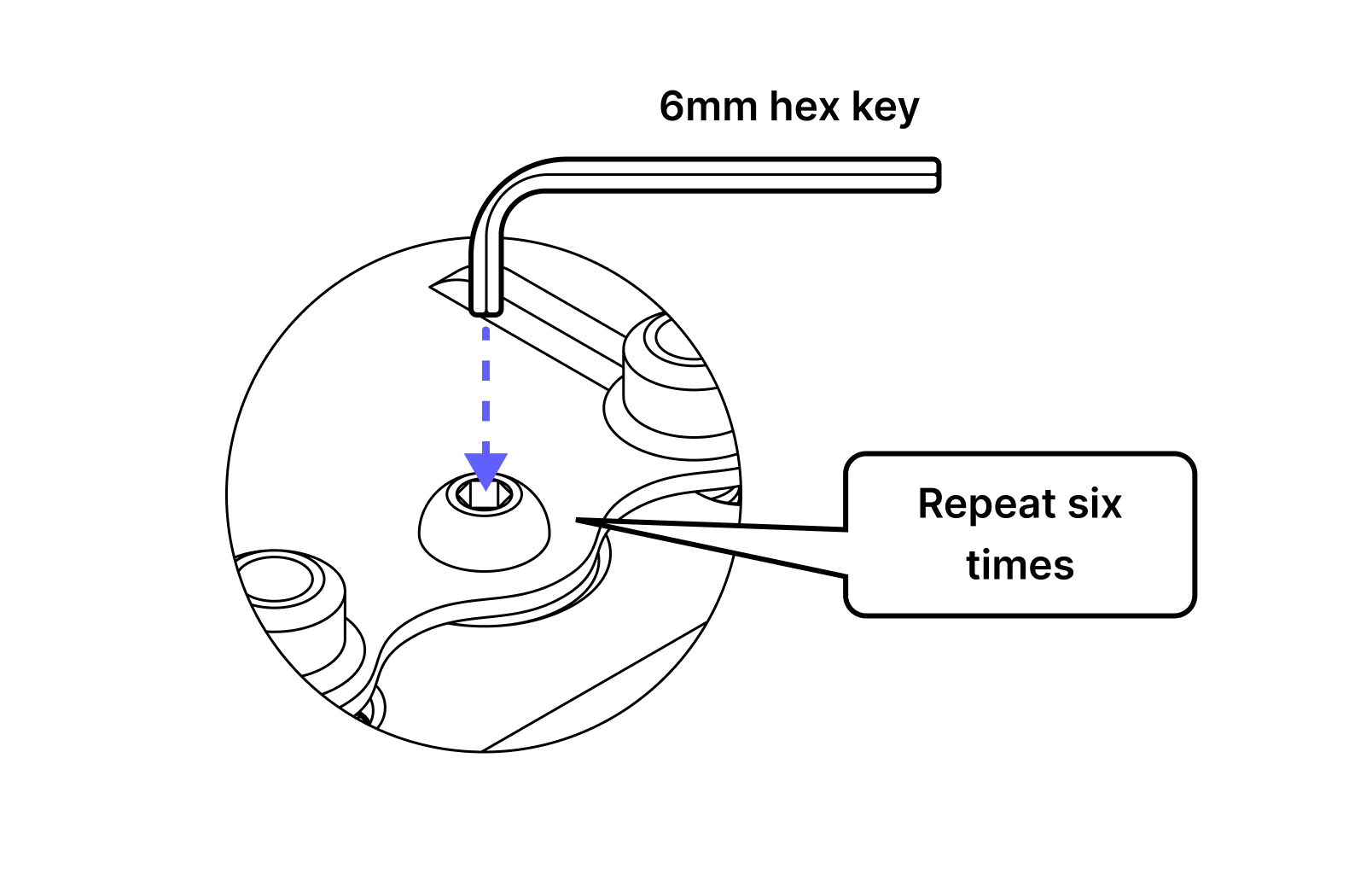
7. Tighten all six adjustment fasteners: 2 on the bottom and 2 on the top for azimuth and 1 each on the front and back for elevation.
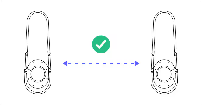
8. Using your GPS app and the coordinates for each site, point the bracket towards the other site.
9. Use the video you took during the site survey and your signal mirrors to help align the two mounting brackets.
10. Loosen the bracket jaws at each site so you can spin the brackets to align with each other.
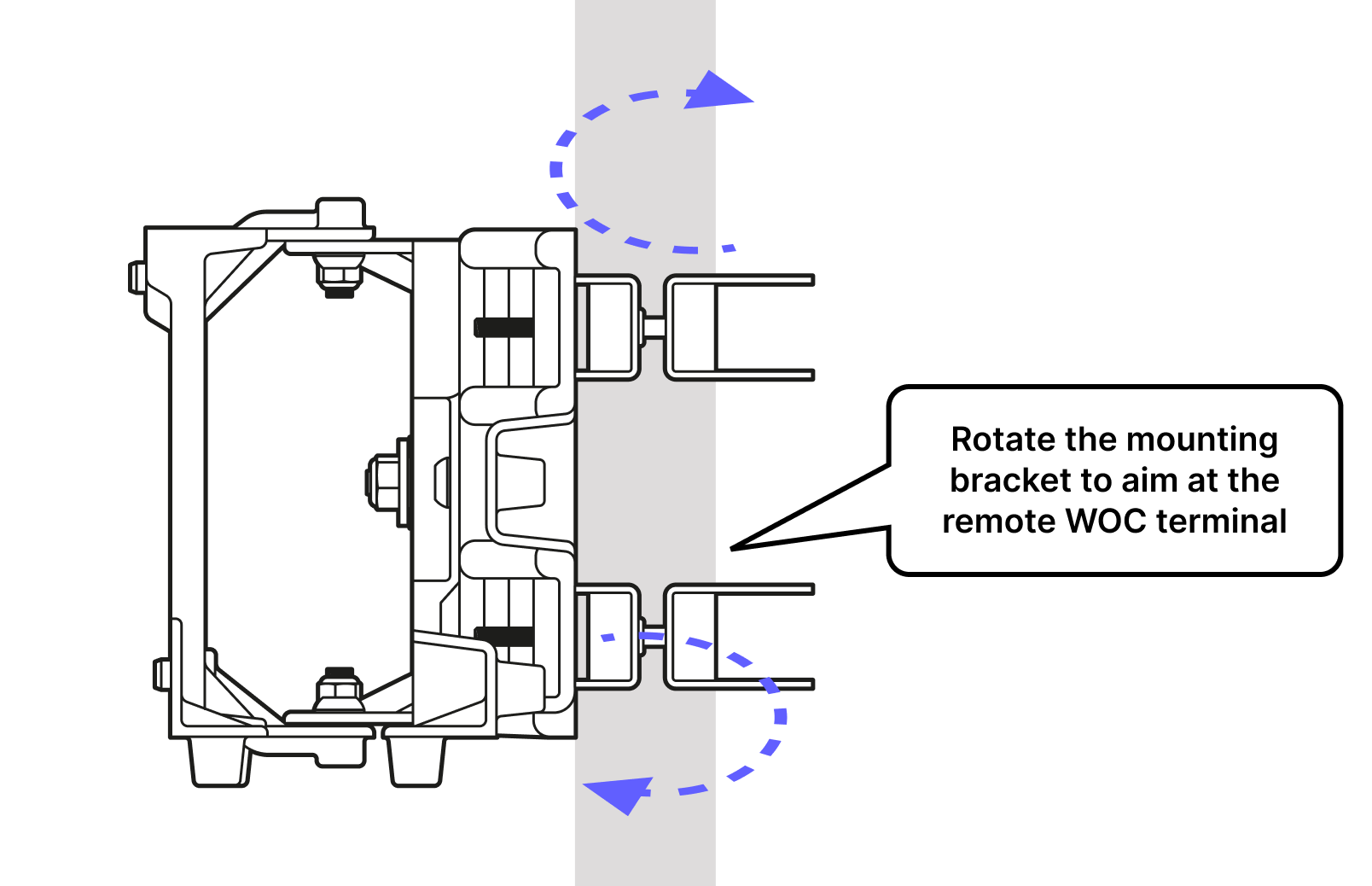
11. Use the face of the bracket as a pointer to align with the other site. It is helpful if the other site is actively flashing with the signalling mirror during this step.

12. Once the bracket is aligned, re-tighten the bolts. Double check the alignment when tight and adjust if necessary.
13.
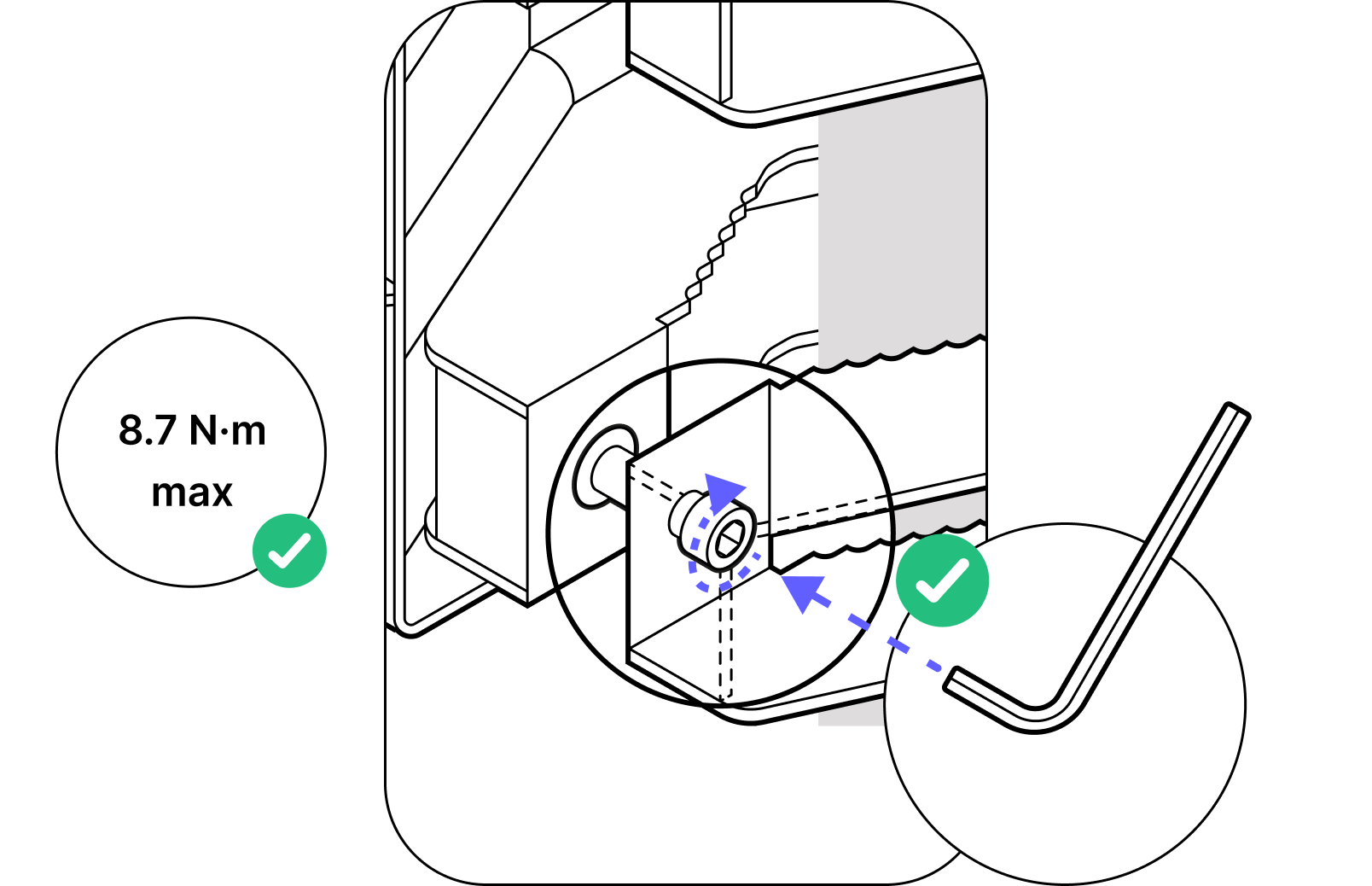
14. The bolts must be tightened to 8.7 N-m with an appropriate torque wrench.
8.2 Installing the WOC terminal
Parts
- 1
WOC terminal
- 2
Assembled Octis RJ45
- 3
Assembled Octis DC
- 4
Assembled Octis SFP
Installation toolkit
- 1
1/4 " ratchet and sockets
- 2
6mm hex key
- 3
5mm hex key
Tips
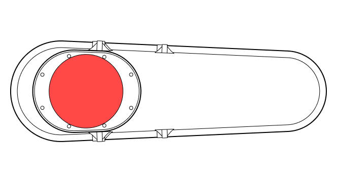
- Red lens cover. Don't forget to remove the red lens cover after physical installation and all connections are verified.
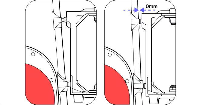
- Mounting fasteners. When tightening the WOC terminal bolts, start with the top two. Tighten the four mounting fasteners to attach the WOC to the pole bracket (8.7 N-m max).
- Do not touch the window beneath the red lens cover. Keep all dust caps and the red lens cover in place until the terminal is mounted and pointed. Avoid touching the window beneath the red lens cover.
- Check all connectors once installed. Gently pull each cable to make sure the cable is secured and does not back out of the connector.
- 1
Do not power on the WOC terminal until directed.
- 2
Make sure that the terminal is securely attached to the fasteners.
- 3
Avoid working in strong winds or unfavorable weather conditions.
- 4
Do not install with any additional load or weight on cables or connectors.
Important
Do not remove the dust caps from the WOC terminal until you are ready to plug in the Octis connector.
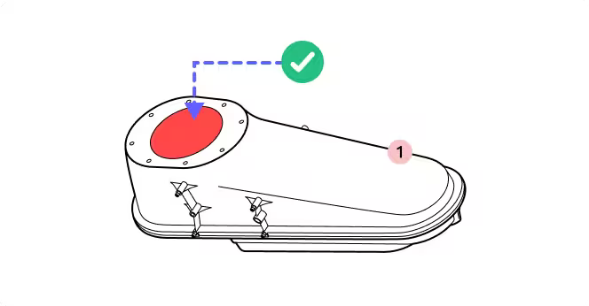
1. Do not remove the red lens cover until explicitly directed.
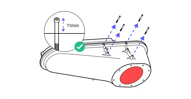
2. Back the pre-installed fasteners to 11mm thread depth to clear the guide pins on the mounting bracket.
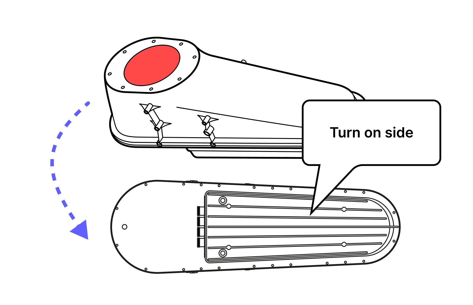
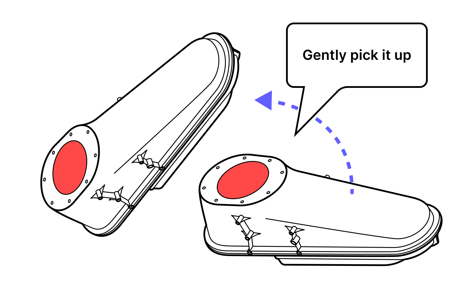
3. Turn the terminal on its side and ensure the dust caps are still in place.
4. Pick up the terminal gently. IMPORTANT: Handle the terminal with care throughout the mounting.
5. Slide the fasteners into the round holes on the mounting bracket and down into the slots for the screws.
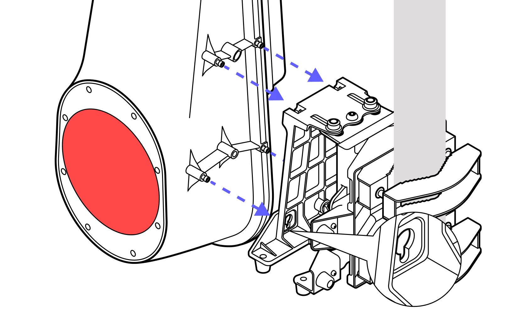
6. Place one hand on the terminal and guide it into place as you tighten the four screws.
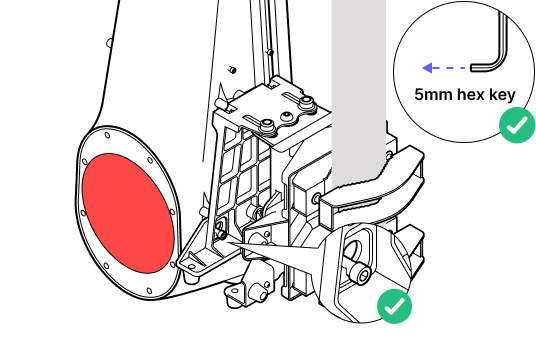
7. Ensure all screws tighten and the terminal is flush to the bracket at all four locations. Screws should be tightened to a torque of 8.7 N-m.
8. Prepare the Octis connectors to be plugged in. Do not remove the dust caps yet.
9. Ensure that the unit is not powered and there is no power going to the DC cable.
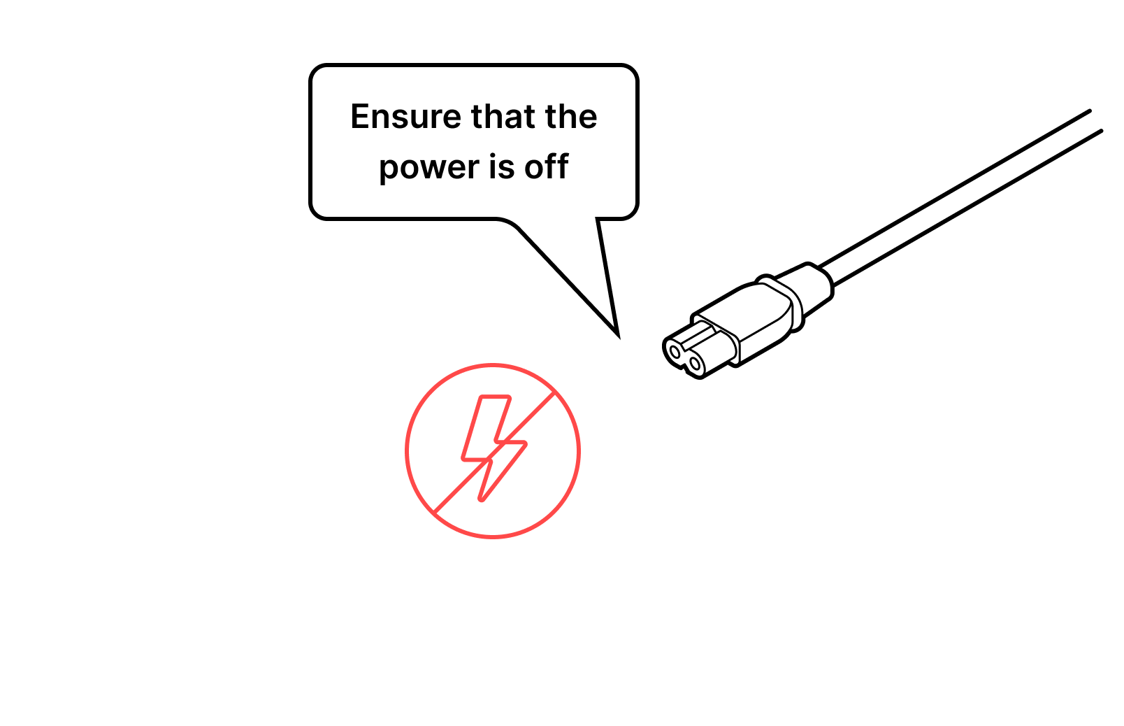
10. Remove the dust caps one by one. DO NOT remove all the dust caps at once.
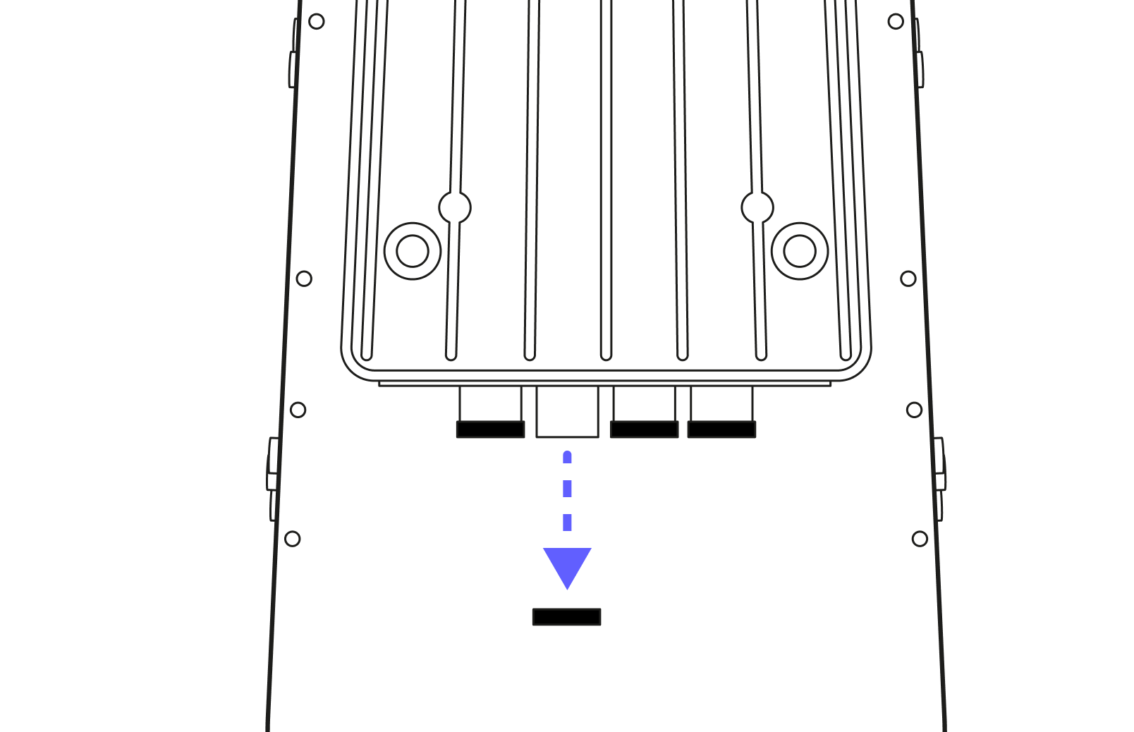
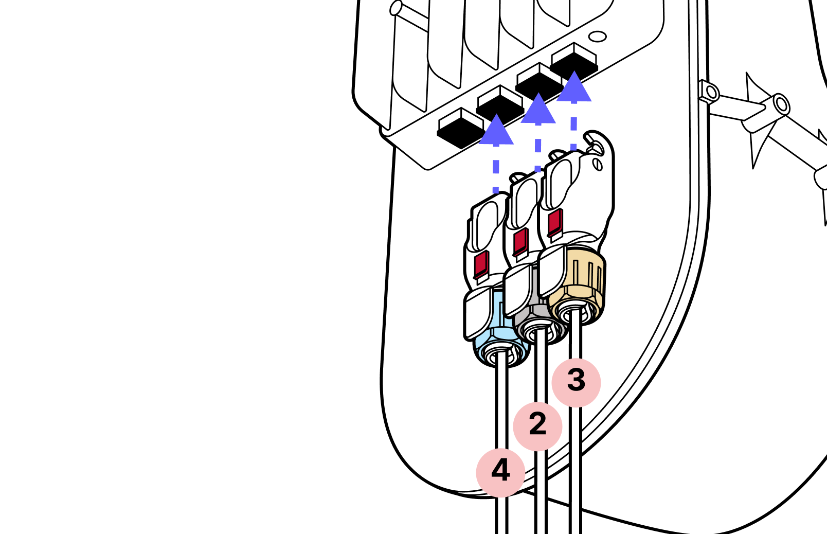
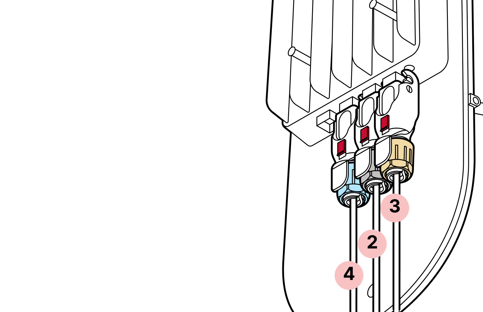
11. Start with the fiber connector(s) (blue cap). For the DC (yellow) and RJ45 (black) connectors it is important to push from the cable, NOT the plastic housing.
12. The proper order of connectors is
- The SFP connector (blue) (both if using 2 SFP connectors)
- The RJ45 connector (black)
- The DC connector (yellow)
The DC connector should be UNPOWERED.
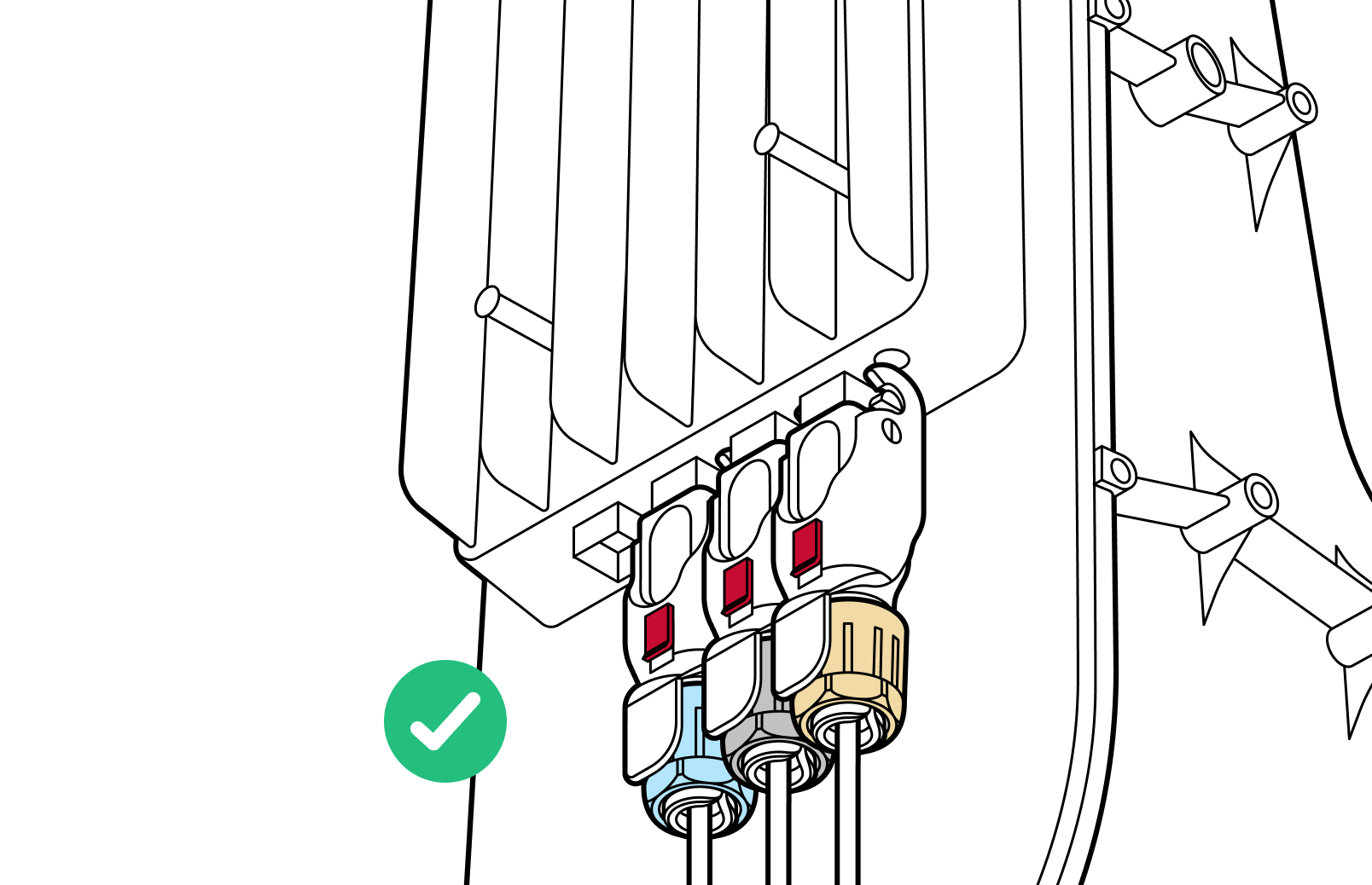
13. Use the black hinge lock to lock the connectors into place and slide the red lock into the locked position.
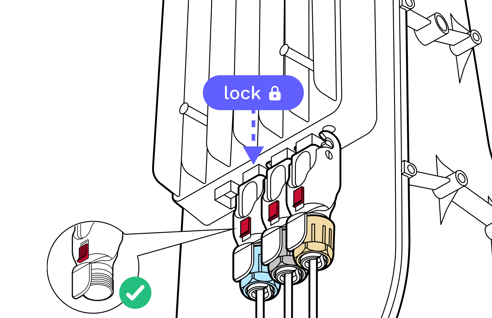
14. Recheck to make sure all the cables are properly seated and locked via both the hinge lock and the red slide lock.
Run Taara Prism
Application feature
Taara Prism can be used by installers to provision, configure, and bring up Taara Lightbridge links. taara.team/taarauniversity - Tutorial video from Taara University.
1. Download the latest Taara Prism from the Taara Partner Portal.

2. Open the Taara Prism.

3. Check the network connectivity to Taara terminals.
3.1. Enter the IP address provided by the Taara team (if provided) or upload a pre-provisioning file if given one.
3.2. Else, enter the default IP addresses.

4. Follow the instructions on screen.
Note: to successfully complete the link provisioning, the Taara Prism needs to be connected to the internet.

5. Set up a second terminal from another site.

6. Taara terminals are now fully provisioned.
9. Network connection
Select one of the connection types
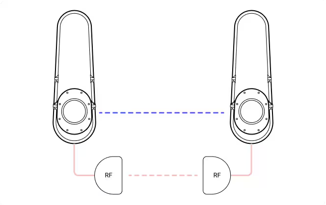
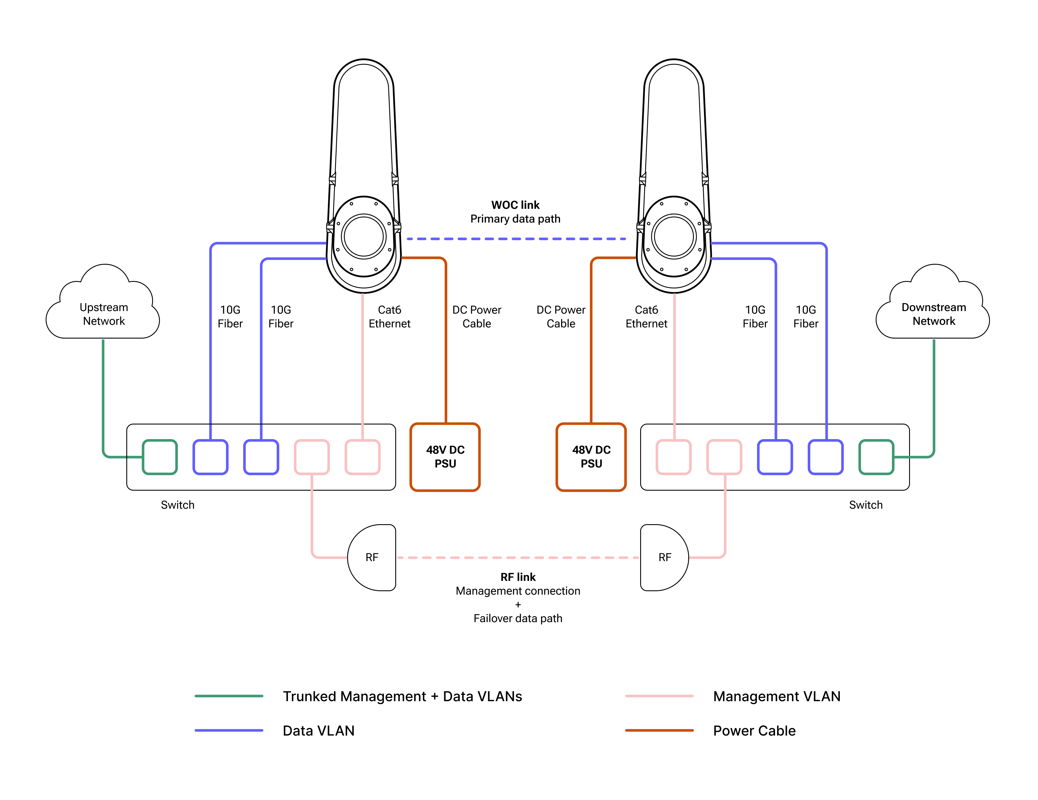
9-A. Out-of-band setup
Ideal for bringing up and operating Taara Lightbridge in brownfield deployments, where operators can route management traffic over an existing fiber or radio connection in their network.
9-B. Standalone operations
Ideal for bringing up and operating Taara Lightbridge in greenfield deployments, where management and data traffic are carried over the same wireless optical channel. The CAT6 cable is still required for initial bring-up, management, and monitoring.
9-A. Out-of-band setup
Typical single Taara Lightbridge link out-of-band setup
Checklist
Management connection:
- Establish the management link by connecting the RJ45 port to the external switch or router.
- If Power over Ethernet (PoE) is used to power up the WOC terminal, connect the Ethernet cable from the RJ45 port of the WOC terminal to the PoE port of the PoE adapter, and connect the Ethernet cable from the LAN port of the PoE adapter to the external switch or router. Make sure the PoE is unpowered when connecting to the terminal.
- Ensure that the management link (e.g., radio or fiber) is up.
Data traffic:
- Connect the 10G fiber cable from the Customer Switch/Router to SFP+ Port 1.
- If required, connect a second 10G fiber cable to SFP+ Port 2.
Telemetry streaming:
- Ensure WOC terminals have the appropriate gateways configured to send telemetry traffic to the Customer Management Network or the Cloud.
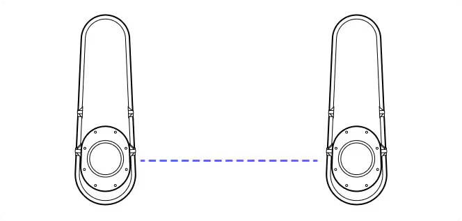
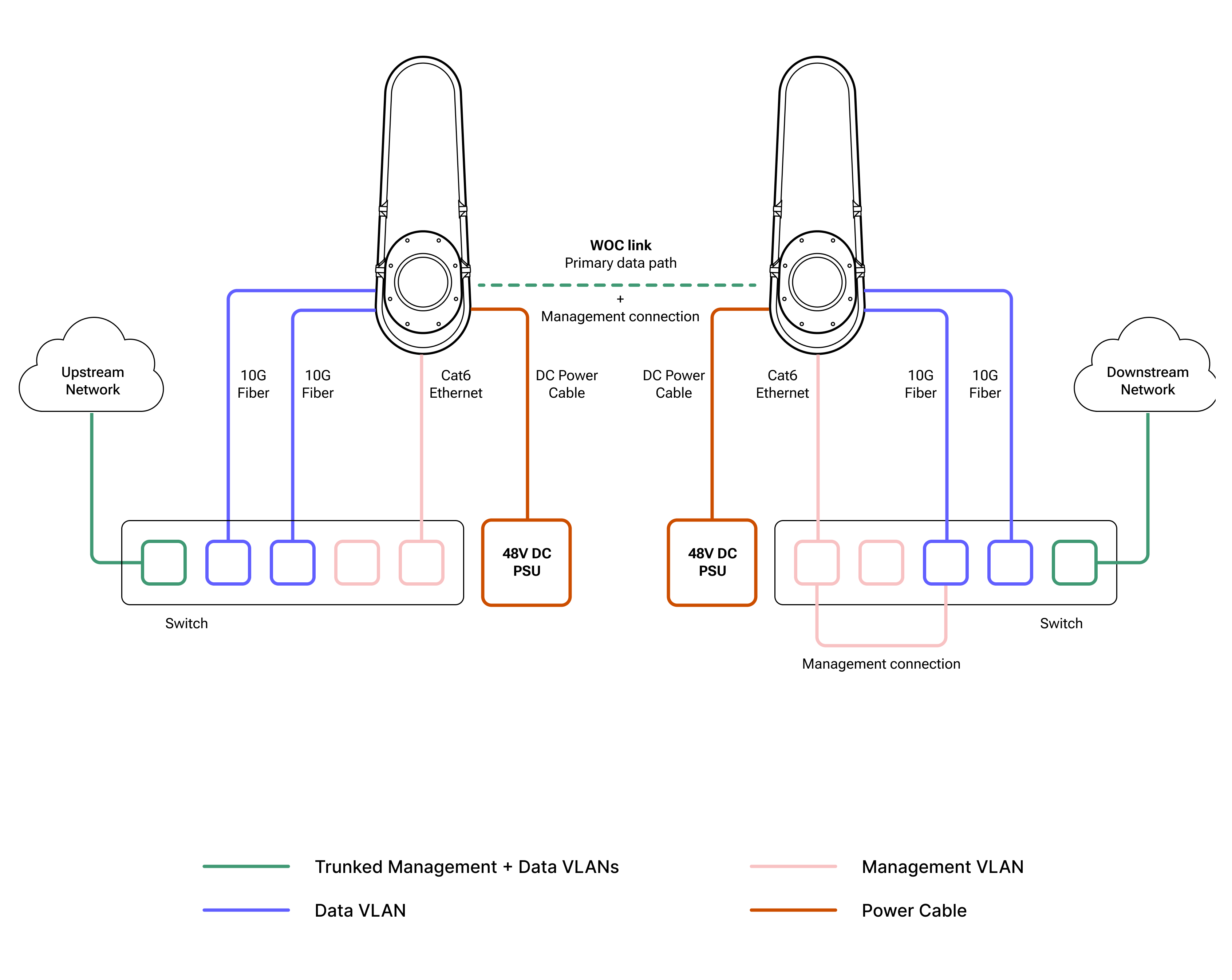
9-B. Standalone operations
Typical single Taara Lightbridge link in-band setup
Checklist
Management connection:
- Establish the management link by connecting the RJ45 port to the external switch or router.
- If Power over Ethernet (PoE) is used to power up the WOC terminal, connect the Ethernet cable from the RJ45 port of the WOC terminal to the PoE port of the PoE adapter, and connect the Ethernet cable from the LAN port of the PoE adapter to the external switch or router.
Data traffic:
- Connect the 10G fiber cable from the Customer Switch/Router to SFP+ Port 1.
- If required, connect a second 10G fiber cable to SFP+ Port 2.
Telemetry streaming:
- Ensure WOC terminals have the appropriate gateways configured to send telemetry traffic to the Customer Management Network or the Cloud.
Additional Instructions
Prerequisites
There is a team at each site location with the Site Survey Toolkit and a laptop with the latest Taara Prism installed.
Step 1: Installer-1 connects to terminal-1 via Taara Prism
Step 2: Installer-2 connects to terminal-2 via Taara Prism
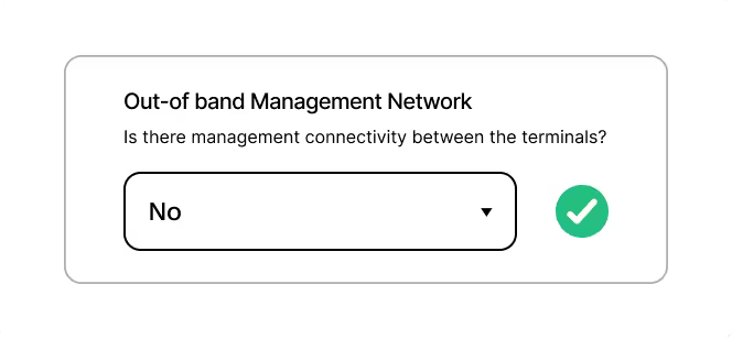
Step 3: Installer-1 and Installer-2
- Terminal settings - No changes.
- Remote terminal settings: Out of band Management network, change it to “NO”.
Please ensure both sides (Installer 1 & 2) have selected the same option to proceed with installation.
- Terminal will reboot with standalone mode enabled.
- Installer-2 follow the same steps in terminal-2.
Step 4: Camera pointing for Installer-1 and Installer-2
- Terminal should be inside the small yellow circle. (This is a requirement for in-band setup.)
Step 5: Raster scan page (Very Important )
- Installer-1: click on “Yes, start Raster scan”
- Installer-2: click on “No”
Step 6: Installer-1 click “Next” to complete the registration
- Installer-2: Exit from Taara Prism
10. Troubleshooting
Terminal not powering up
Symptoms: Terminal is not reachable, the terminal mirrors do not make noise after power is applied, the Ethernet connection cannot be established, or the port does not come up.
Fix: Unplug power and disconnect the CAT6 Octis cable. Re-check that the RJ45 extends the correct length outside the connector body with the cap installed. Ensure the RJ45 does not slide back into the Octis housing. Tighten the gland nut, then reinsert the cable by holding the cable and pushing upward—do not push by holding the connector body.
Terminal not reachable
Symptoms: Cannot ping the terminal or Prism is not connecting to the terminal.
Fix: Ensure the Ethernet port is coming up (for example, LEDs are lit). Confirm that your computer is configured with a static IP address in the same range as the terminal. The terminal default IP address is 192.168.111.2.
Fiber ports not coming up
Symptoms: Fiber ports do not come up on the switch or router.
Fix: Ensure compatible SFP modules are being used and that they match the correct wavelengths. Bidirectional modules are not supported. Verify that the fiber connectors and SFP modules are clean, and ensure the LC connectors are fully inserted.
11. Have more questions?
If you have any questions, you can always send us an email at support@taaraconnect.com