This guide provides instructions for network engineers to seamlessly integrate Taara Lightbridge into their existing infrastructure. Taara Lightbridge is composed of two terminals establishing a wireless optical communication (WOC) link.
Understanding the Taara Lightbridge Interface
Taara Lightbridge provides three ports of connectivity:
- Two 10 GbE optical SFP+ ports for primary data traffic.
- One 1G RJ-45 Ethernet port for out-of-band management and link telemetry.
Figure 1. Taara Lightbridge terminal. SFP+ and Ethernet ports use autonegotiation and cannot be hard-coded for full or half-duplex.
Deployment Solutions
Select the integration method that best fits your infrastructure needs:
- Out-of-band setup
- Standalone operations
- Link aggregation
Solution 1. Out-of-Band Setup
Out-of-band (OOB) setup is recommended for customers requiring high availability, enabling traffic to switch over to a backup fiber or wireless radiofrequency (RF) if necessary. This setup uses customers’ L2 network switches to manage the remote terminal during a link outage.
- Technology: Multiple Spanning Tree Protocol (MSTP) is recommended for loop prevention and fast traffic convergence within 1 to 3 seconds.
- Note: All Layer 2 configuration should be made on your switch. For the switchover to work, hybrid mode must be enabled on the channel used. Please reach out to Taara Support at support@taaraconnect.com if you want to ensure the hybrid mode is enabled for your Taara Lightbridge link.
- Capacity: Normal operation provides 10 or 20 Gbps. If switchover is configured, set the quality of service (QoS) to limit throughput to the backup link capacity, e.g., < 1 Gbps.
- Note: Limiting the throughput over the backup link is important to ensure priority traffic flow and make sure that the link does not saturate, which prevents passing overheads and control.
- Management connection: The side channel provides OOB remote terminal management and an inter-terminal messaging connection.
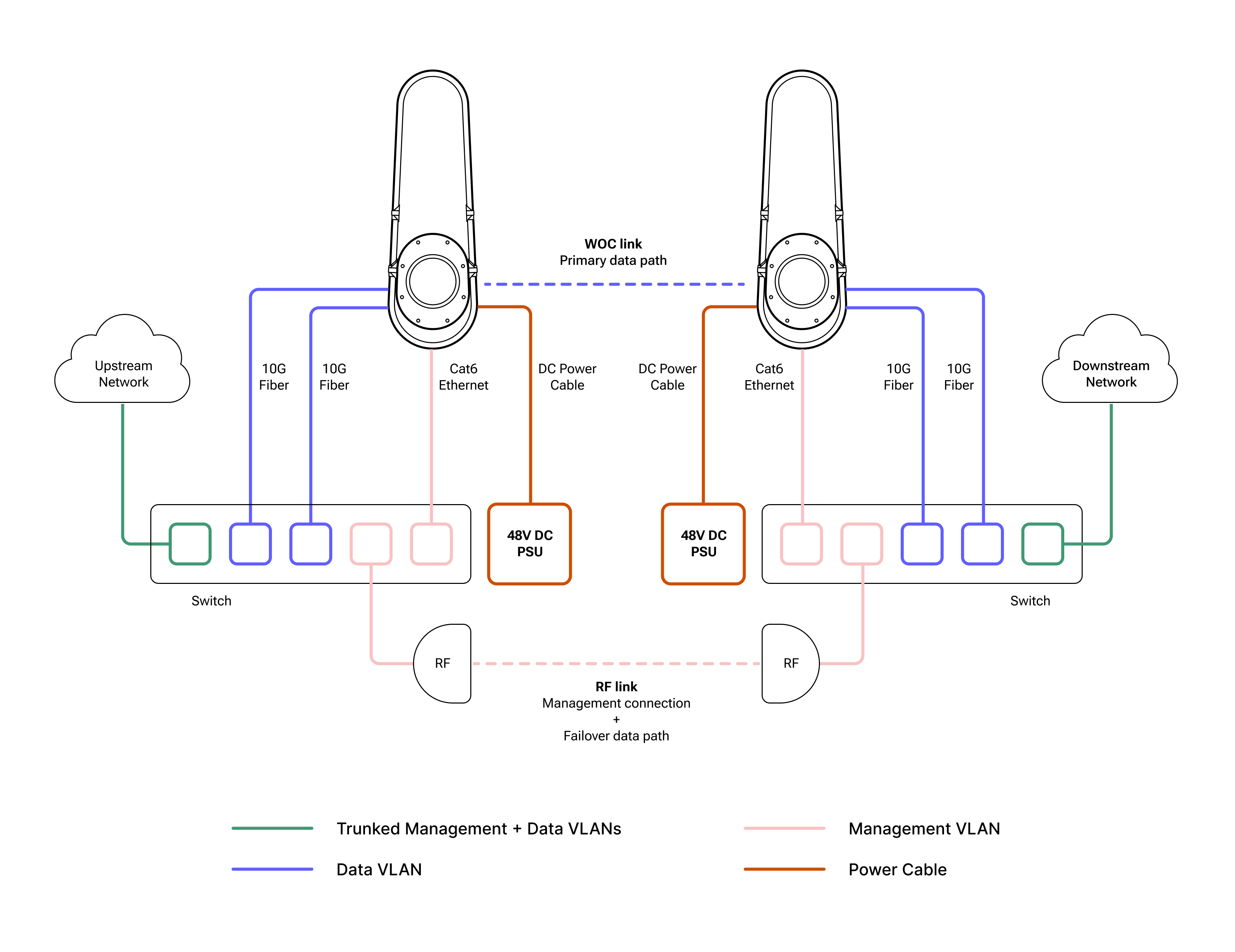
Figure 2. A typical Taara Lightbridge link OOB setup. Management connection can be over fiber or radio.
Solution 2. Standalone Operations
Standalone operations is ideal when a backup link or side channel is not available. This setup allows management traffic to travel over the primary WOC data channel.
- Requirement: Requires external Layer 2 switches at both sites.
- Connectivity: The 10 Gbps SFP+ port is configured as a trunk to carry both data and management VLANs.
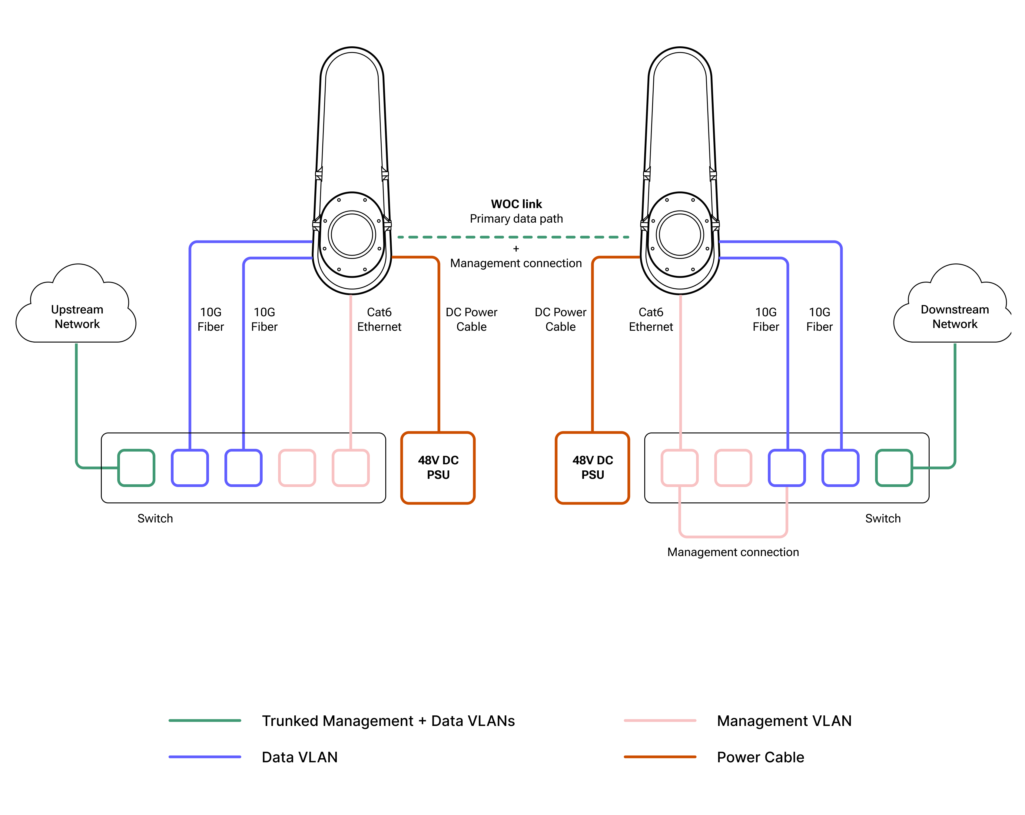
Figure 2. A typical Taara Lightbridge link standalone operations.
Solution 3. Link Aggregation
To maximize capacity, both 10 Gbps SFP+ ports can be combined into a single 20 Gbps interface on the client switch.
- Constraint: Requires Layer 3 configuration to handle network failover.
- Configuration: Both ends of the link aggregation (LAG) must be configured identically on your network devices.
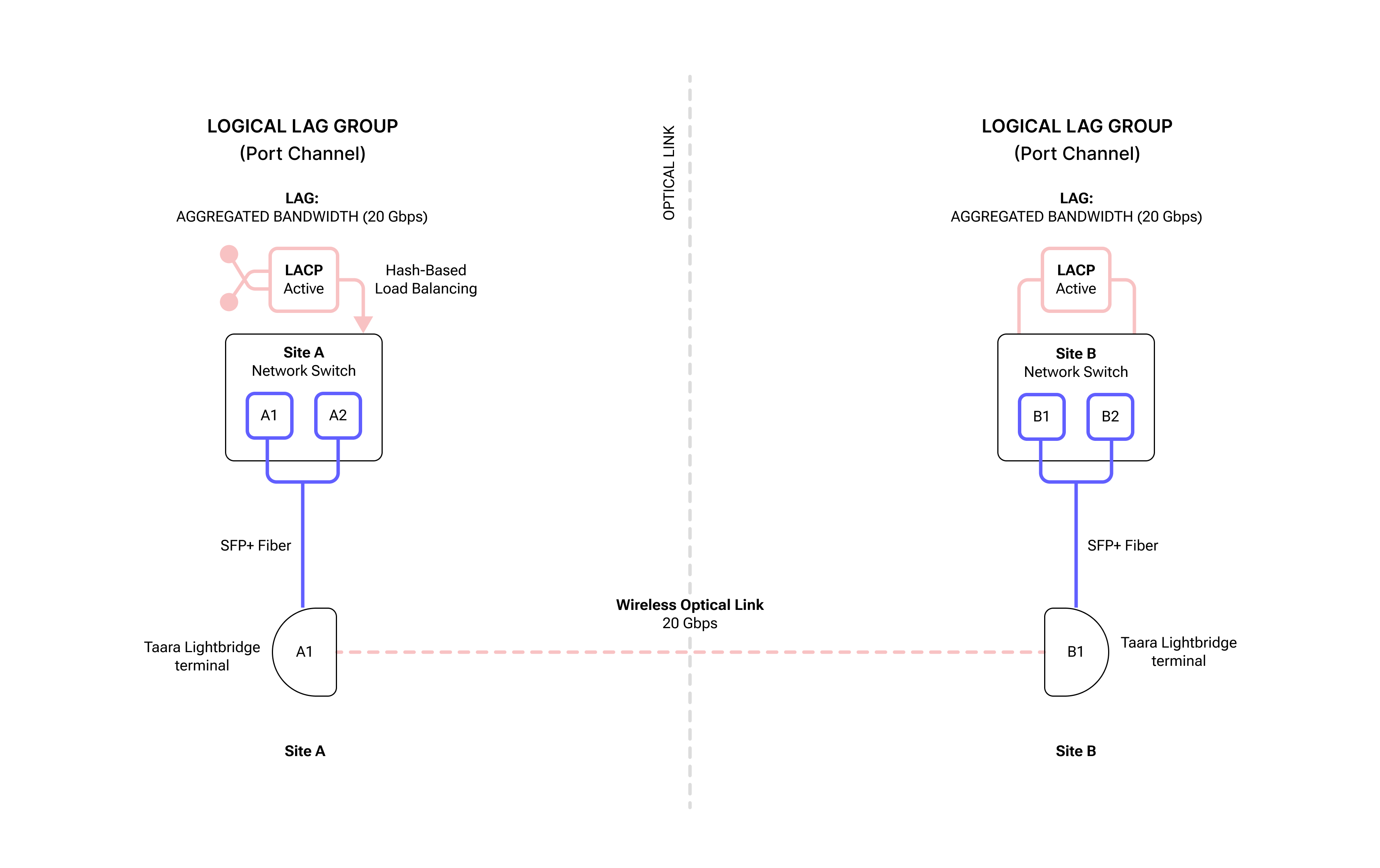
Figure 3. A typical Taara Lightbridge link set up for link aggregation. The 2 x 10 Gbps connections, A1 and A2 at Site A, and B1 and B2 at Site B, have been aggregated to 20 Gbps.
Core Switch Configuration for OOB Setup
The following steps outline the setup for a standard deployment for Solutions 1 and 2:
- VLAN Tagging and Untagging: Configure the backup port on the switch as a trunk to allow both management and data traffic.
- Multiple Spanning Tree Protocol: Allow prioritization of switchover traffic through different links for maximum availability if backup is required.
- Quality of Service (QoS): Allow prioritization of management and high-priority traffic during switchover congestion by pushing this traffic to the front of the data queue if backup link is configured over the side channel.
VLAN Setup
Tagging is used when a port needs to carry traffic for multiple VLANs simultaneously. In this case, configure a Management VLAN and select the Trunk or Data VLAN option. This is typically done for switch-to-switch links (trunks).
IMPORTANT
Please refer to your network equipment vendor’s documentation on how to configure VLANs correctly.
VLAN capability (IEEE 802.1Q standard) on the networking switches is a fundamental requirement for setting up the management and data traffic switchover on Taara Lightbridge. The configuration terminology (Syntax) can vary slightly depending on the vendor equipment you are working with.
Make configurations on the data port as a trunk to allow both management and data traffic. Below are the basic parameters required for VLAN Configuration. Taara Lightbridge data interface will act as a bridge to the remote terminal’s data port.
Tagging a VLAN
- Interface ID: The physical port number (e.g.,
GigabitEthernet1/0/1orEth1). - VLAN ID: The specific number (1–4094) assigned to the network segment.
- Encapsulation Type: Usually 802.1Q, the industry standard.
- Allowed VLAN List: A definition of which tagged VLANs are permitted to pass through that specific port.
- Native VLAN (optional, recommended): Defines which VLAN handles untagged traffic arriving on this tagged port to prevent "VLAN leaking."
Untagging a VLAN
Untagging is used for Access Ports. Access Ports is where you connect the Taara Lightbridge Management Interface which does not support/understand VLAN tags. The switch strips the tag before sending data to the device and adds it back when receiving data.
- Interface ID: The physical port identity.
- Port VLAN ID: This is the most critical parameter. It tells the switch, "Any traffic coming into this port without a tag belongs to VLAN X."
- Interface Mode: Set to Access or Untagged.
- VLAN Assignment: The single VLAN ID that the port is a member of.
MSTP Configuration
To configure MSTP, define the specific parameters that allow switches to identify themselves as part of the same logical region. For switches to share MSTP information and collaborate on a loop-free topology, their configuration must be identical across several key attributes.
IMPORTANT
Please refer to your network equipment vendor’s documentation on how to configure STP/MSTP correctly.
The parameters are generally divided into Region Configuration, which must match across all switches in a group, and Instance/Interface Parameters, which control traffic flow.
Mandatory Region Identification Parameters
For two switches to be in the same MST Region, these three parameters must match exactly. If any of these differ, the switches will treat each other as being in different regions, leading to a suboptimal Common Spanning Tree (CST) behavior:
- Region Name: A user-defined alphanumeric string (e.g., "REGION_ONE"). It identifies the logical boundary of the MST region.
- Revision Number: A 16-bit numerical value (0–65535). This is a manual versioning tool: when you change the VLAN-to-Instance mapping, increment this number across all switches to ensure they remain synchronized.
- VLAN-to-Instance Mapping: This defines which VLANs belong to which MST Instance (MSTI). By default, all VLANs are mapped to Instance 0, also known as the Internal Spanning Tree (IST).
Note: The switches actually compare a 16-byte MD5 signature (digest) of this mapping table. This is not configured manually, but it is generated based on your VLAN assignments.
MST Instance (MSTI) Parameters
Once the region is defined, configure individual instances to manage load balancing:
- Instance ID: A number (typically 1–64) representing a specific spanning tree topology.
- Bridge Priority: Similar to standard STP, this determines which switch becomes the Root Bridge for that specific instance. It is usually set in increments of 4096 (e.g., 4096, 8192, 32768).
Interface and Global Parameters
These settings tune how MSTP interacts with specific links or the rest of the network:
- Path Cost: Determines the "cost" of using an interface. MSTP uses Long Mode (32-bit) values by default to support high-speed Links like 10G or 100G.
- Port Priority: Used to break ties when a switch has multiple paths to the root bridge.
- Max Hops: Unlike the "Max Age" timer in standard STP, MSTP uses a hop count (default is usually 20) to limit the propagation of BPDUs (Bridge Protocol Data Units) within a region.
- Timers (Hello, Forward Delay, Max Age): These are usually inherited from the CIST (Common Internal Spanning Tree) and are often left at default values.
Quality of Service
The QOS configuration is used to prioritize management and/or high-priority traffic on a switchover configuration to mitigate traffic congestion.
To make the below configurations on the switch, please refer to your network equipment vendor’s documentation on how to configure QOS correctly.
- Classify: Create a class-map for Management & Priority traffic VLAN.
- Policy: Set cos-queue 7 for management & Priority traffic.
- Traffic Shaping: Rate-limit the egress backup port to match the side channel capacity.
- Throughput: Limit the throughput over the backup link to avoid side channel congestion.
The Foundation: Performance Metrics
Before configuring QOS on the switch, define the targets for these four primary metrics:
- Bandwidth: The total data rate or throughput allocated to specific traffic.
- Latency: The time it takes for a packet to travel from source to destination. This is crucial for voice and video.
- Jitter: The variation in the delay of received packets. High jitter causes "stuttering" in real-time communication.
- Packet Loss: The percentage of packets that fail to reach their destination. TCP can handle some loss, but UDP (used for voice) cannot.
Classification and Marking
Instruct the network how to recognize different types of traffic:
- Classification: Identifying traffic based on ACLs (Access Control Lists), IP addresses, port numbers (e.g., Port 443 for HTTPS), or VLANs.
- Marking: Once identified, the traffic is "tagged:"
- Layer 2: Uses Class of Service (CoS) bits in the Ethernet frame header.
- Layer 3: Uses Differentiated Services Code Point (DSCP) values in the IP header. This is the industry standard.
Congestion Management (Queueing)
When a link is full, the router must decide which packets to send first. For queuing algorithms, choose a strategy:
- Priority Queuing (PQ): High-priority always goes first.
- Weighted Fair Queuing (WFQ): Gives a fair share of bandwidth based on weight.
- Low Latency Queuing (LLQ): A hybrid that provides a "strict priority" lane for voice/video.
Congestion Avoidance
This manages the queue before it gets completely full to prevent a total "tail drop,” where all incoming packets are discarded.
- WRED (Weighted Random Early Detection): Randomly drops lower-priority packets as the buffer fills up to signal the sender (TCP) to slow down, preventing global synchronization of traffic bursts.
Configuring Link Aggregation
To maximize link capacity on Taara Lightbridge, link aggregation (LAG) is defined in IEEE 802.3ad and requires precise coordination between two networking devices. If the parameters don't match, you’ll likely end up with a "down/down" status or, worse, a switching loop. Please refer to your network equipment vendor’s documentation on how to configure LAG correctly. Below are the basic parameters you need to get a LAG up and running.
Physical Layer Consistency
Before the software can bundle the links, the physical characteristics of the member ports must be identical. If these don't match, the aggregation will fail.
- Speed and Duplex: All ports must operate at the same speed (e.g., 10 Gbps) and be set to full-duplex.
- Media Type: While some modern switches allow mixing, it is best practice to use the same medium (all fiber or all copper) for all links in the bundle.
Logical Configuration Parameters
Once the physical requirements are met, the logical settings on the Port Channel interface must match.
- VLAN Membership: All physical ports must belong to the same VLAN or be configured as the same trunk type.
- Trunking Encapsulation: If using a trunk, both sides must use the same protocol, typically 802.1Q.
- Allowed VLANs: The list of VLANs permitted to pass through the LAG must be identical on both ends.
- STP (Spanning Tree) Settings: STP treats the LAG as a single logical interface. Ensure path costs and priorities are consistent to avoid unexpected blocking.
The Negotiation Protocol
Decide how the two devices will "talk" to each other to form the group.
| № | PROTOCOL | DESCRIPTION | BEST FOR |
| 1. | LACP (802.3ad) | Link Aggregation Control Protocol. The industry standard. | Multi-vendor environments. |
| 2. | PAgP | Port Aggregation Protocol. Cisco proprietary. | Legacy Cisco-only environments. |
| 3. | Static (On) | No negotiation protocol. | Simple setups, but lacks switchover intelligence. |
Hash Algorithms (Load Balancing)
The Load Balancing Hash determines how traffic is distributed across the physical links. While this doesn't have to strictly match on both ends for the link to stay up, mismatched algorithms can cause uneven traffic distribution. Common parameters include:
- Source/Destination MAC Address
- Source/Destination IP Address
- TCP/UDP Port numbers (L4 hashing)
Best Practice: The "LACP System ID"
For LACP to work, the devices exchange System Priorities and Port Priorities. The device with the lower System Priority becomes the "Master" and decides which ports are active in the bundle if you have more physical links than the bundle's maximum limit.
Note: Ensure that the "Max Bundle" limit (typically 8 or 16 ports) is supported by the hardware at both ends if you intend to utilize LAG for two or more Taara Lightbridge terminals connecting to a single switch.
Taara Prism
Taara Prism is an element management system for Taara Lightbridge. To enable performance monitoring, management, and FCAPS for Taara Lightbridge, download Taara Prism from the Taara Partner Portal at partner.taaraconnect.com.
Frequently Asked Questions
Below are frequently asked questions on integrating Taara Lightbridge into operator networks:
Can I use any brand of network devices with Taara Lightbridge?
Yes. Taara Lightbridge can support any brand and type of network devices as long as your network device supports 10 Gbps SFP+ ports and you are using 1 Gbps Ethernet port for management traffic. Please refer to Interface Specifications on the Product Data Sheet.
Can I aggregate both channels on Taara Lightbridge to obtain 20 Gbps of throughput?
You can aggregate the 2 x 10 Gbps SFP+ data ports using LAG, also known as port channel, but they need to run Layer 3. See Configuring Link Aggregation section.
What are the limitations for configuring LAG?
- Port feature constraints: When a port becomes a member of a LAG, it surrenders its individual identity to the logical interface. Consequently, many layer 2 and security features are strictly prohibited on member ports.
- Strict Physical Parameter matching: For a LAG to successfully form and aggregate traffic, all member ports must have 100% identical physical properties. If there is a mismatch, the switch will error out or LACP will automatically suspend the non-compliant link.
- Protocol Limitations: While some advanced enterprise switches let you assign up to 16 or 32 ports to a single LAG for cold-standby redundancy, standard LACP dictates a maximum of 8 active ports operating simultaneously in a single bundle. Also, depending on the switch ASIC architecture, there is a hard limit on the overall number of distinct LAG groups a single switch (or a stacked switch fabric) can support—ranging anywhere from 8 trunks on low-cost switches up to 64 or 128 on high-density enterprise gear. Lastly, standard LAG requires all member ports to terminate on the exact same physical switch. To span a LAG across separate physical hardware units, the switches must support specialized multi-chassis architectures like Stacking, Virtual Switching System (VSS), or Multi-Chassis EtherChannel (vPC/mLAG).
Can I run different protocols on this lightbride WOC link?
Yes. Taara Lightbridge is protocol agnostic, meaning it can transparently carry any Ethernet-based Layer 2 (e.g. VLAN, MPLS) or Layer 3 (e.g. IPv4, IPv6) traffic without specific configuration on the terminals themselves.
With L2 Configured with an STP/MSTP switch, how long does it take for traffic to switch over to a backup during a link outage?
Taara Lightbridge supports MSTP configurations to switch traffic between ports. The switchover is configured to happen about 1 to 3 seconds after a link outage is detected.
Do you have VLAN tagging on the terminals and management ports?
No,Taara Lightbridge does not support IEEE 802.1q configurations. Both the 1 Gbps management Ethernet port and 10 Gbps SPF+ ports for data traffic are untagged by default, i.e
- Management traffic to and from Lightbridge has no VLAN TAG
- Data traffic to and from the Lightbridge is handled in Trunk mode. It can carry tagged or untagged traffic.
The customer may however configure any VLAN for both management and/or data in their networking switches towards the network.
What is the difference between Taara Lightbridge and radio?
Taara Lightbridge employs wireless optical communication to transmit data through the atmosphere over focused light beams, i.e., photons, whereas wireless radio like microwave or millimeter wave use electromagnetic waves instead. Taara Lightbridge delivers speeds comparable to fiber optics without requiring the physical cable infrastructure. Moreover, in contrast to radiofrequency, Taara Lightbridge is not subject to signal interference.
Can Taara Lightbridge run on full or half duplex?
Taara Lightbridge’s SFP+ and Ethernet ports are configured to autonegotiate and cannot be hardcoded to full or half-duplex. If the product is not negotiating correctly, please reach out to Taara Support at support@taaraconnect.com.
Can Taara Lightbridge support 1 Gbps on 10 Gbps SFP+ port?
No. Taara Lightbridge does not support 1 Gbps for the data port. You must have 10 Gbps SFP+ on the switch or router connecting to Taara Lightbridge. If you have a specific requirement to support 1 Gbps, please reach out to Taara Support at support@taaraconnect.com, and we’re happy to discuss possible solutions.