Parts List
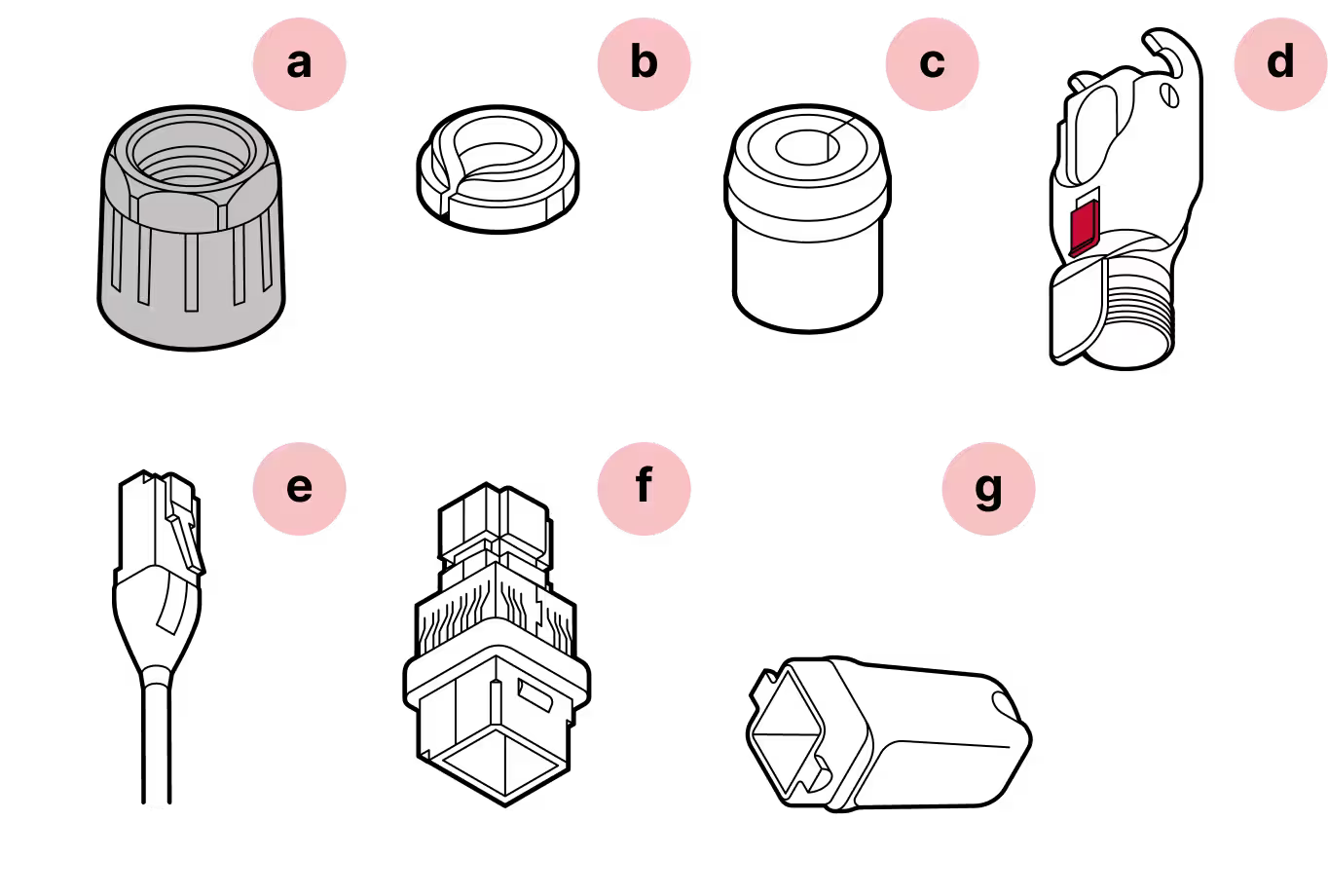
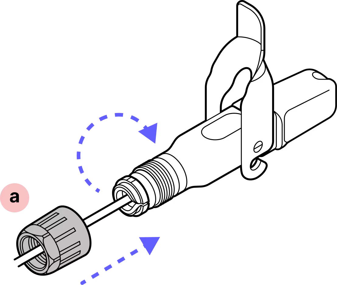
- a
Black gland nut
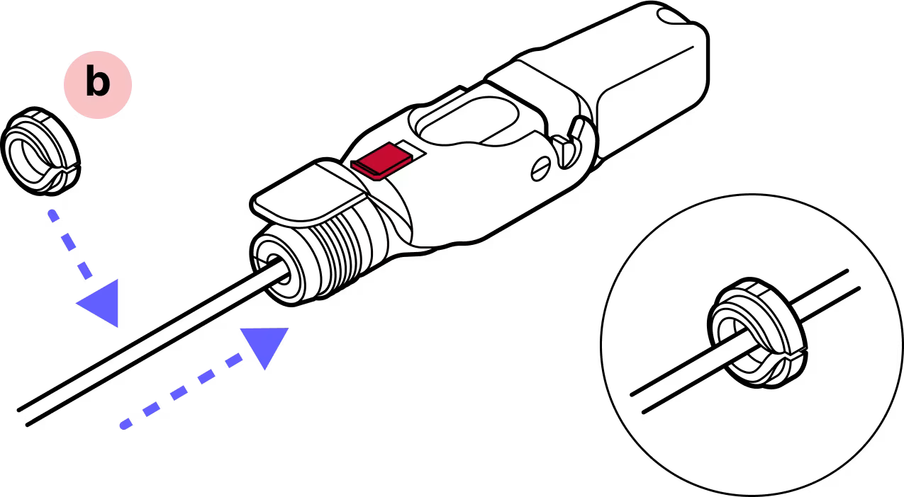
- b
Tightening cone
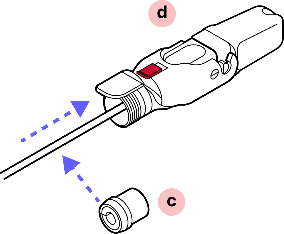
- c
Split rubber gland
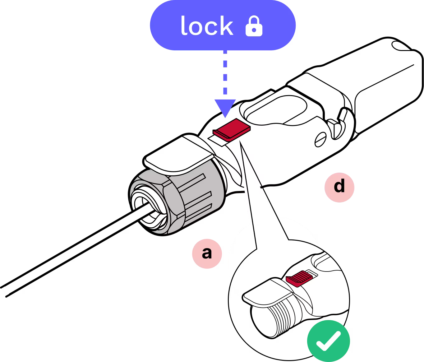
- d
Housing
- e
CAT6 patch cable (in accessory box)
- f
Cable holder
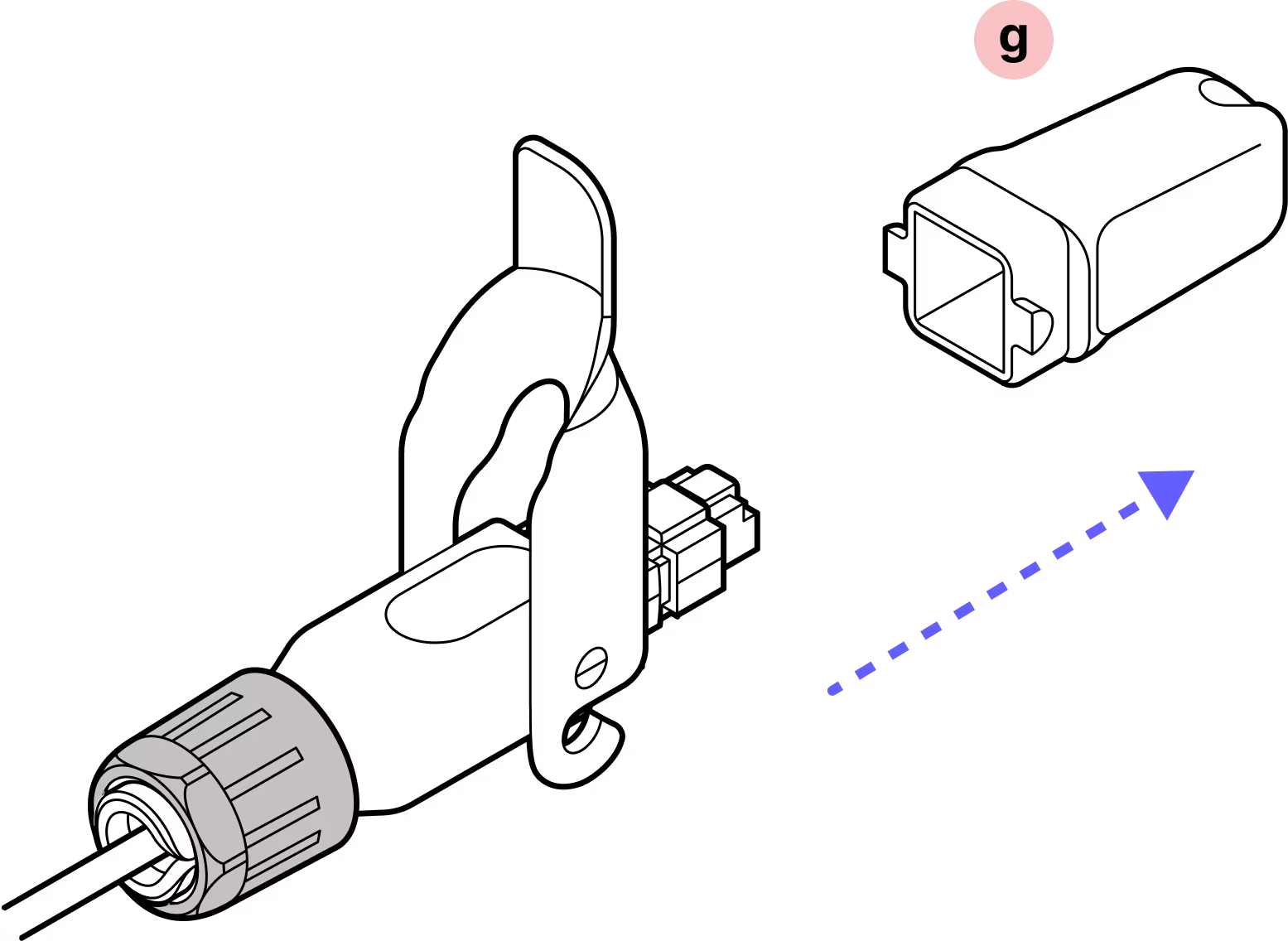
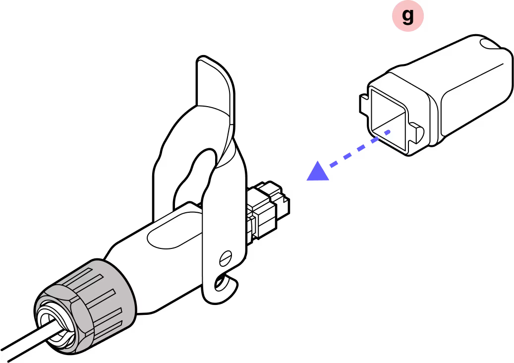
- g
Plug cap
Required Tools

Wire cutters
Assembly
Installation
Step 1
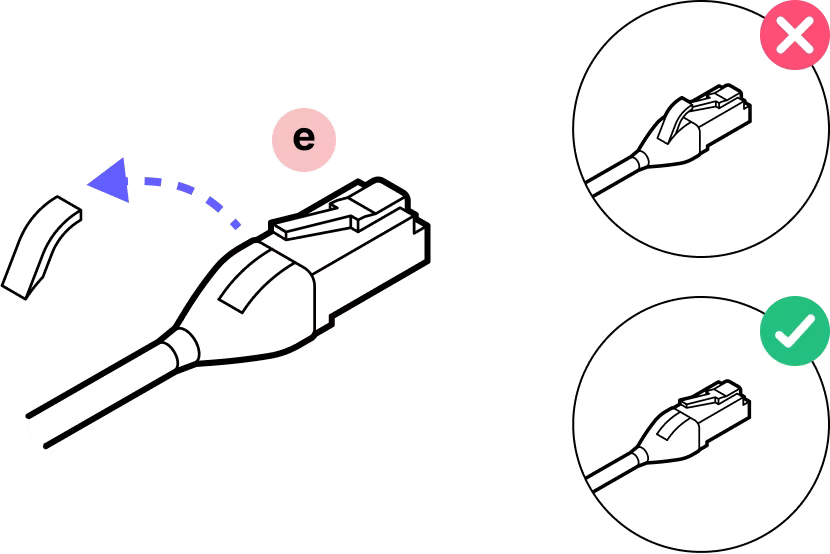
The patch cable comes with a boot over the connector. Remove this material.
Step 2
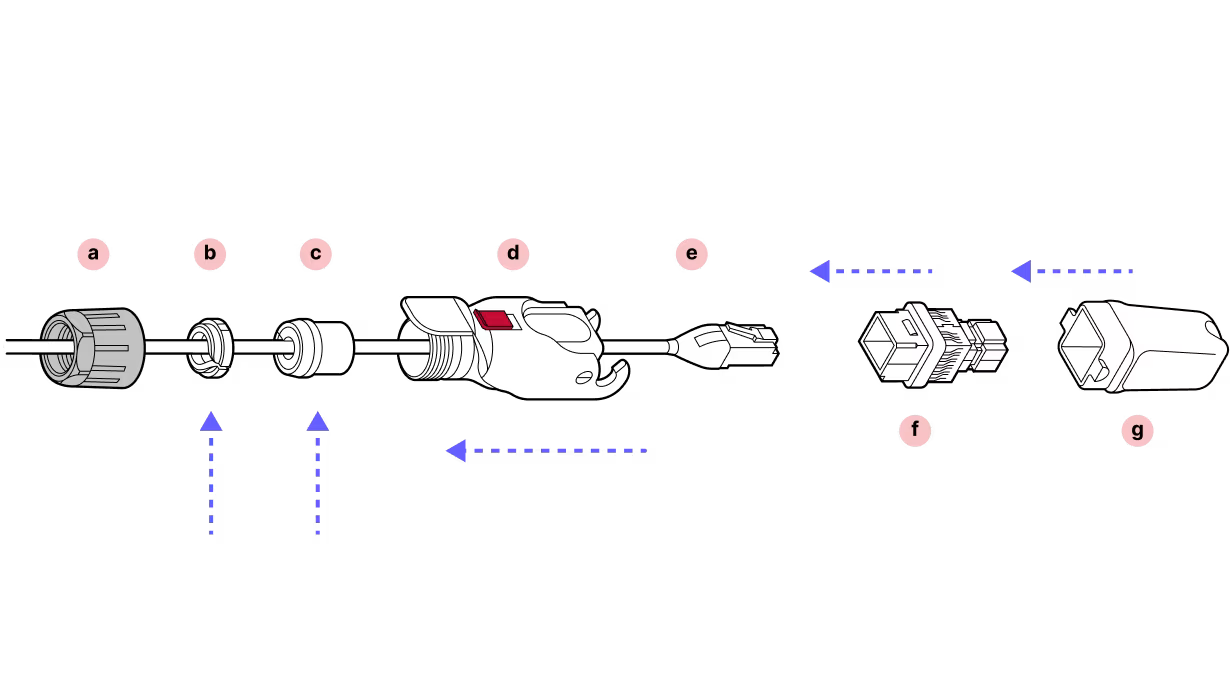
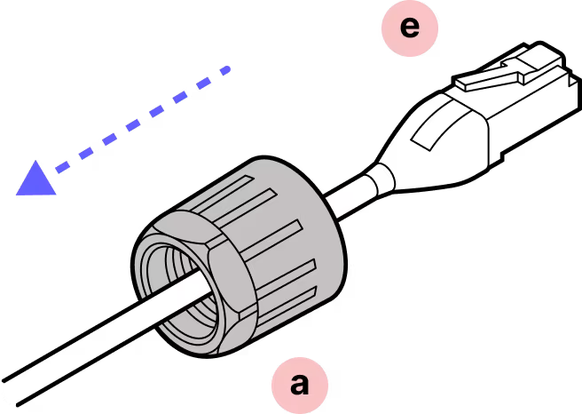
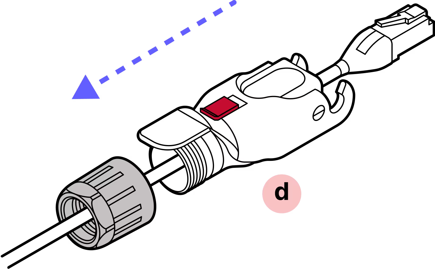
Slide the black gland nut over the cable in the proper orientation.
Step 3
With the plastic connector tab facing up on the cable and the red slide lock on top of the housing, slide the housing onto the cable.
Step 4
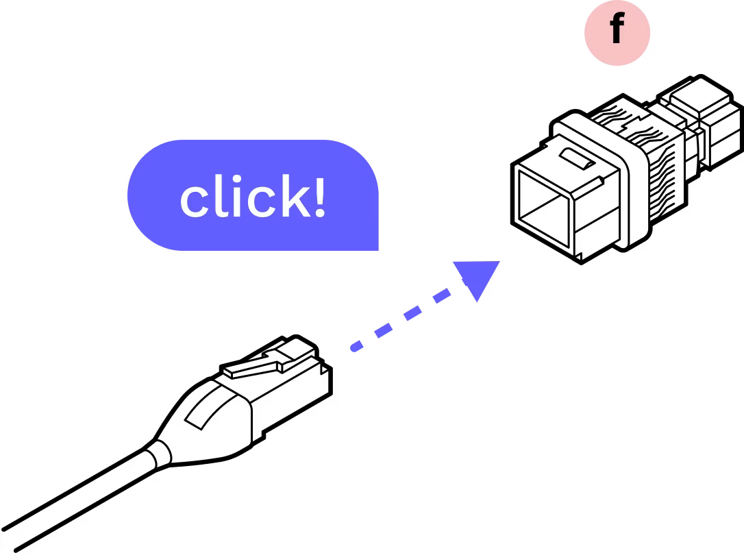
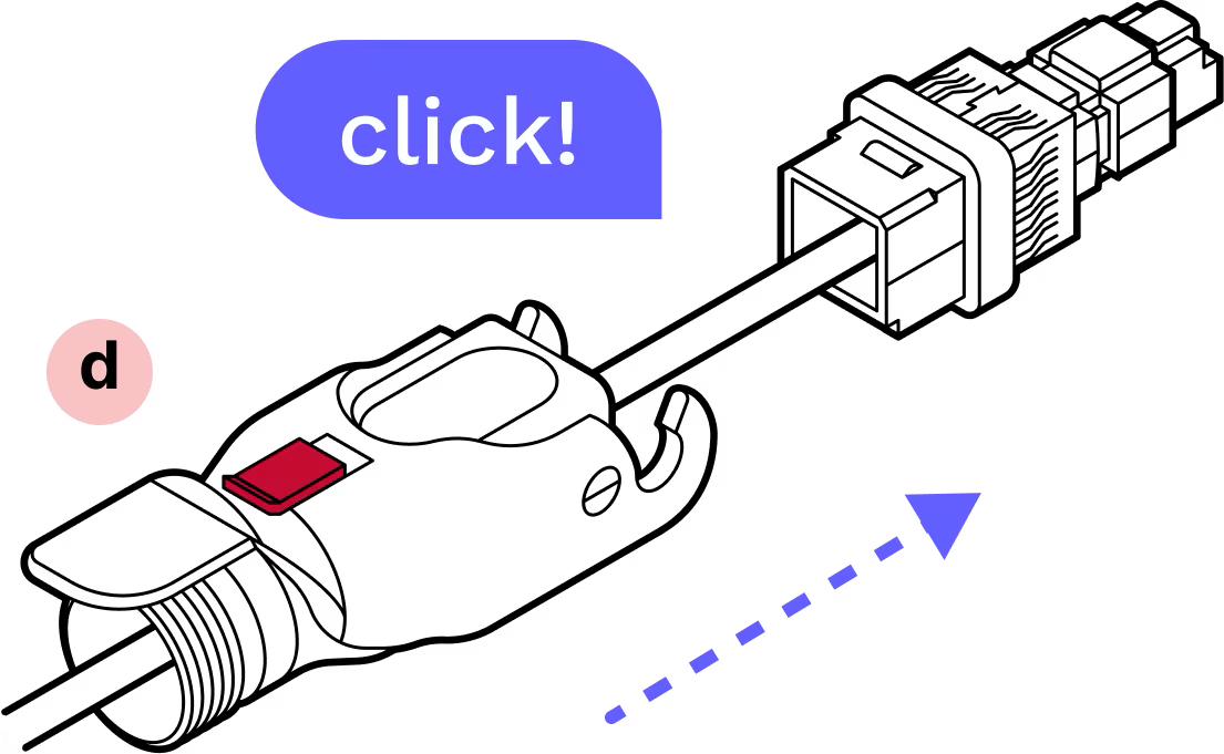
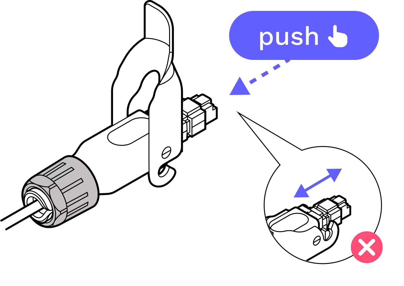
IMPORTANT: Push with the cable, not the connector. Push the cable into the metal housing until it clicks into place and is firmly seated.
Step 5
You will hear a click that signals that the cable is fully inserted.
Step 6
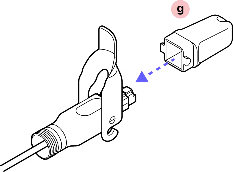
Attach the plastic cap and lock the hinge to ensure that everything stays aligned and in place.
Step 7
Slide the split rubber gland onto the cable in the proper orientation and insert it into the cylindrical part of the Octis housing.
Step 8
Slide the tightening cone onto the cable in the proper orientation.
Step 9
Screw the black gland nut into place. IMPORTANT: The gland nut must be tightened so that the red slide lock catches on its edge in the locked position, but not so tight that the hinge cannot fully close without breaking the red lock. DO NOT OVER-TIGHTEN.
Step 10
Remove the dust cap.
Step 11
Make sure that the connector protrudes the proper distance. The connector should protrude to the flared edges of the cap.
Step 12
Push the connector to ensure it does not slide back. If it does, tighten the black plastic gland nut further or disassemble and go through the previous steps again.
Step 13
Replace the dust cap.
Step 14
Close the red slide lock. IMPORTANT: When closing the hinged lock, the red lock MUST be in the UNLOCKED position. Do not force the hinge lock down or you may break the red slide lock.
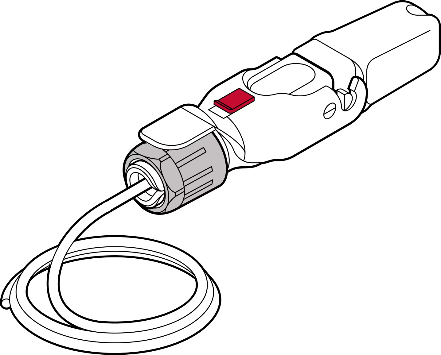
Complete!
Tips:
Check RJ45 depth and nut indication
Double check the RJ45 connector depth using the marking line on the dust cap and make sure the plastic nut is firmly tightened so the cable does not slip. On the Octis cap, use the arrow to verify the length of the visible RJ45 connector (11 millimeters). This is shown in Step 11.
Modify Ethernet cable
Modify the boot on the Ethernet patch cable: the RJ45 connector must be bare, with no rubber boot, rubber lock tab protector, or other protrusions. Use care to avoid damaging the cable or the Octis RJ45 connector.
Gently press down to check
To confirm the RJ45 connector is securely locked in place, apply finger pressure.
Do not remove the dust caps from the WOC terminal until you are ready to plug in the Octis connector.
Last updated: April 2026