Required Tools
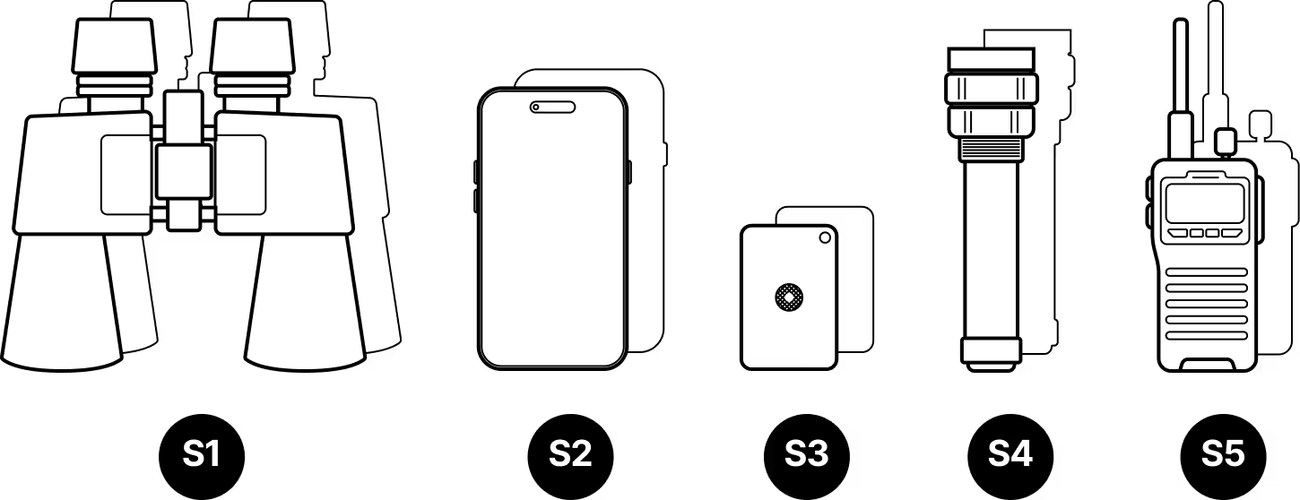
Site Survey
- S1
Binoculars (x2, one for each site)
- S2
Mobile phone with camera (x2)
- S3
Signaling mirror (x2)
- S4
High-powered flashlight (x2)
- S5
Walkie-talkie (if no cell coverage) (x2)
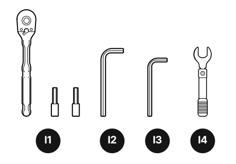
Installation Tools
- I1
¼-inch ratchet and sockets
- I2
6 mm hex key
- I3
5 mm hex key
- I4
Torque wrench (not provided)
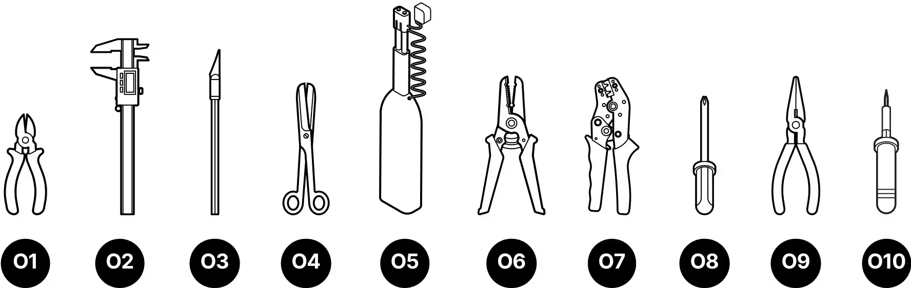
Octis Connector Assemblies
- O1
Wire cutters
- O2
Digital calipers
- O3
X-acto knife
- O4
Scissors
- O5
LC fiber cleaner
- O6
Wire strippers
- O7
Wire crimping tool
- O8
Screwdriver
- O9
Pliers (if not using wire crimping tool)
- O10
Soldering kit (if not using wire crimping tool)
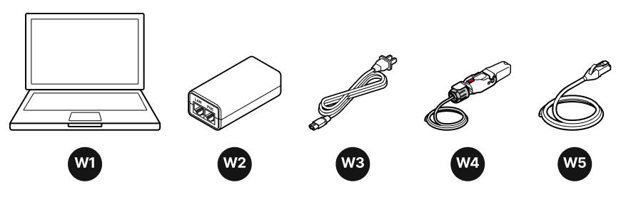
Wireless Optical Communication (WOC) Provisioning
- W1
Laptop
- W2
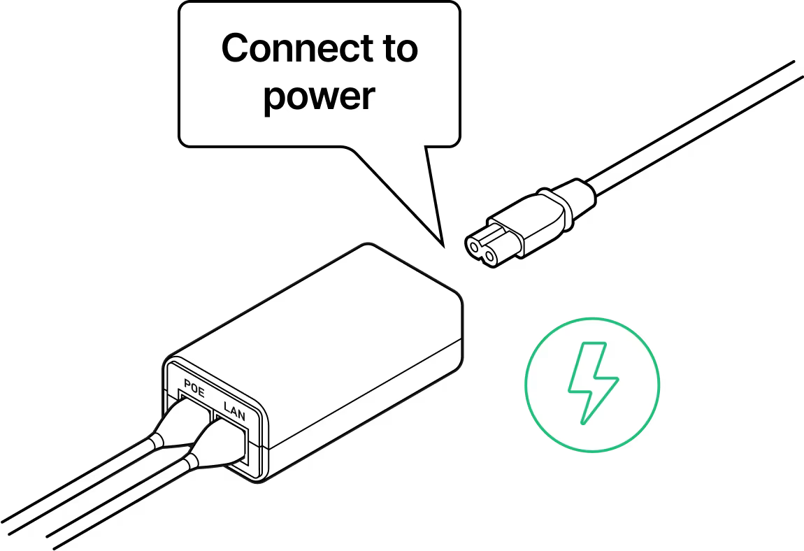
PoE Injector
- W3
Power cord (comes with PoE Injector)
- W4
RJ45 pigtail
- W5
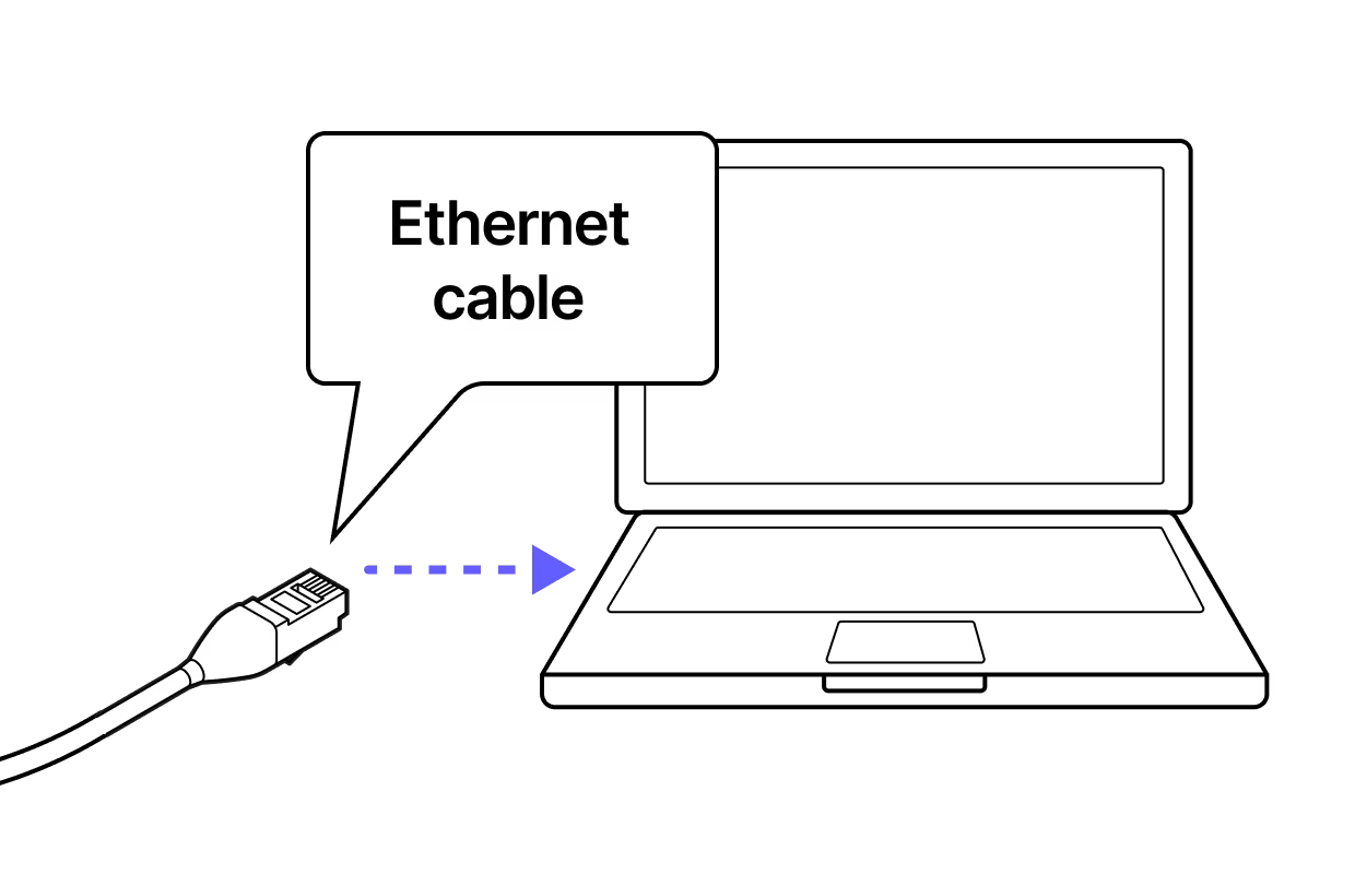
Ethernet Cable (not provided)
Equipment Handling & Safety
Do not remove the dust caps from the WOC terminal until you are ready to plug in the Octis connectors.
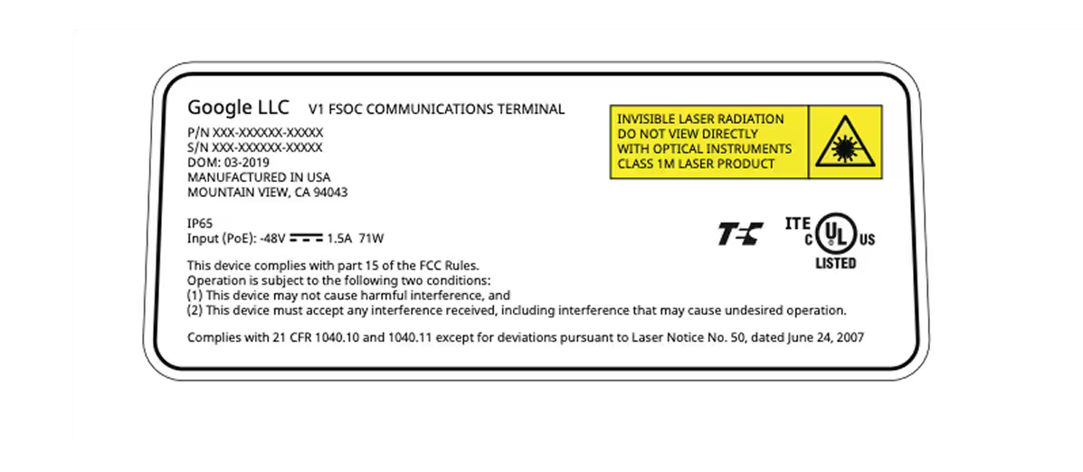
Do not remove labels
The labels on the terminal describe the regulatory compliance and manufacturing details.
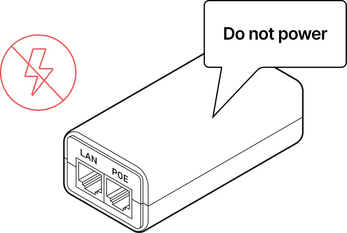
Do not power on the WOC terminal until directed.
Qualified personnel only
Only personnel who have gone through the Taara University training may install the WOC terminals.
No field servicing
WOC terminal cannot be opened or serviced in the field.
Do not touch the window
Keep all dust caps and the red lens cover in place until the terminal is mounted and pointed. Avoid touching the window beneath the red lens cover.
Carrying the terminal
The terminal contains delicate optical equipment and must be carried with both hands. When lifted to higher locations, such as a cell tower, it should be placed in a harness bag and lifted carefully to avoid damage.
Pre-Provisioning and System Health Check
PREREQUISITES: Assemble the Octis RJ45 cable. See Guide Octis RJ45 Connector Assembly for instructions. Lay the unit on its side. DO NOT remove the red lens cover.
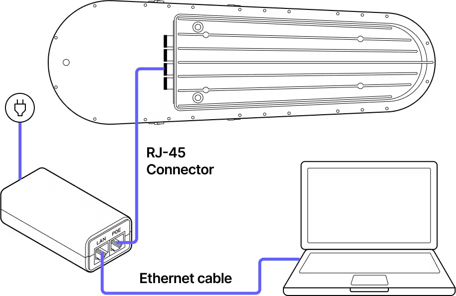
Provisioning Wiring Diagram
Step 1
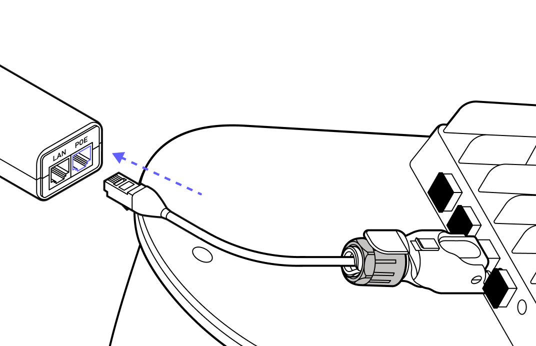
Step 2
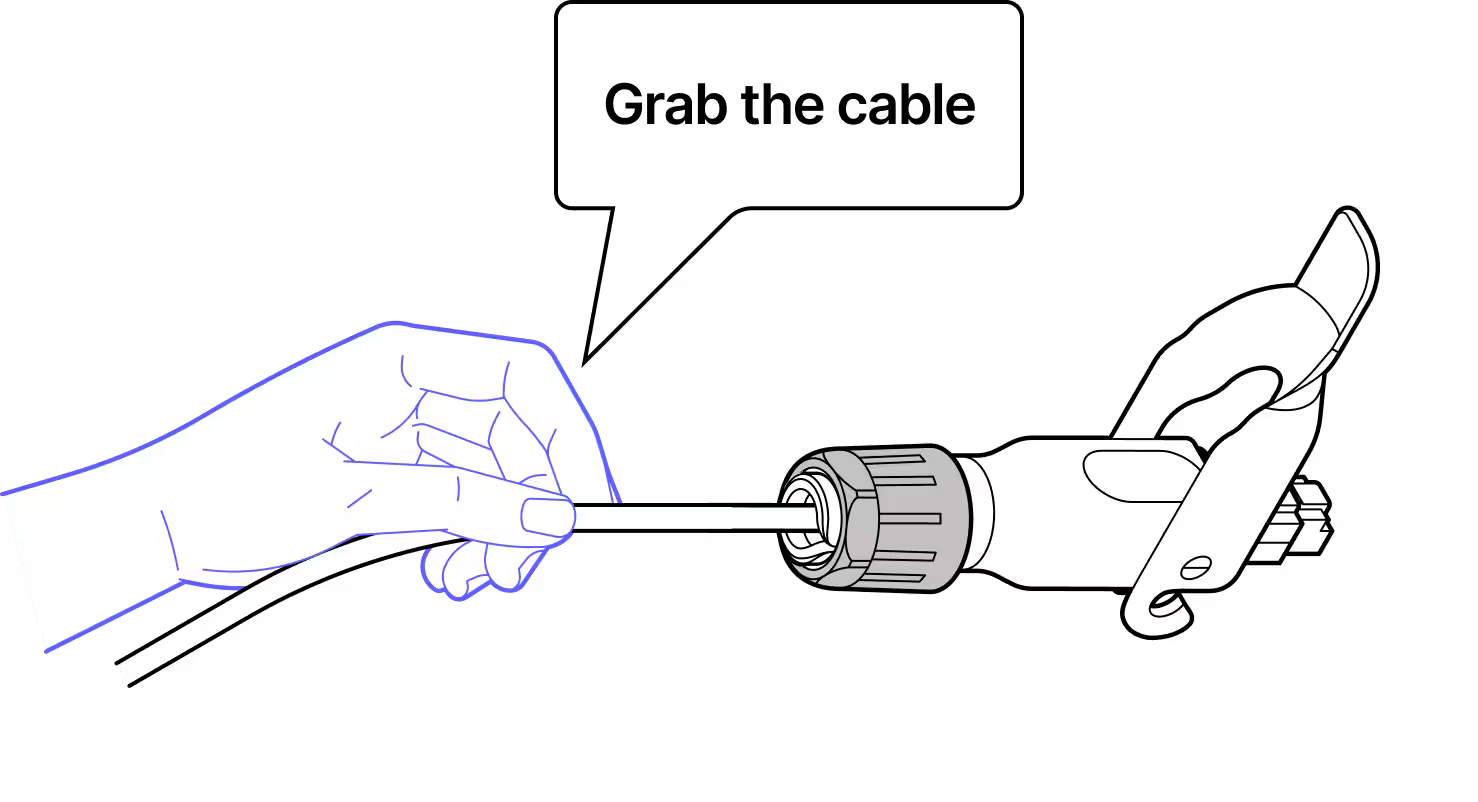
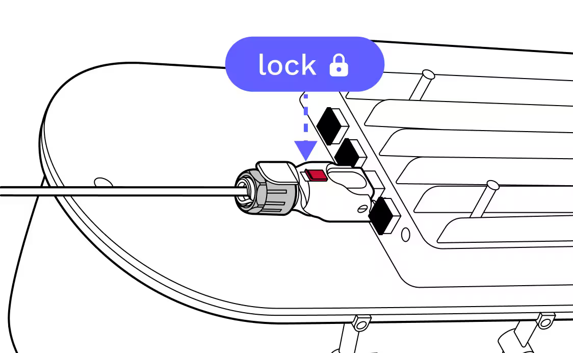
While pushing with the cable, not the connector, plug the RJ45 connector into the terminal and lock it into place.
Step 3
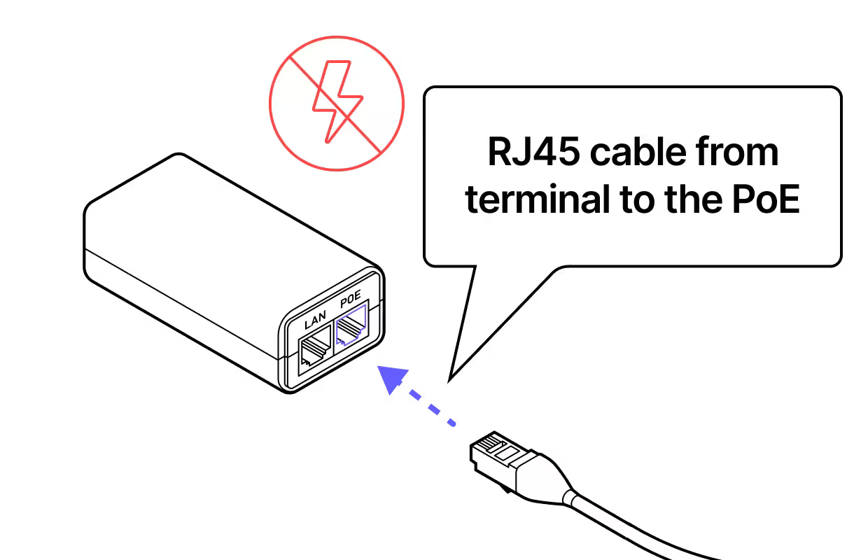
Step 4
Plug the other end of the ethernet cable into the PoE injector.
Step 5
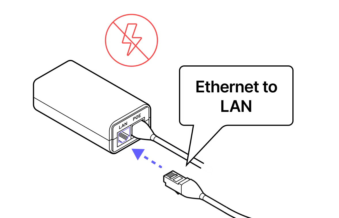
Step 6
Use an ethernet cable to connect the PoE injector to the LAN port on the laptop.
Step 7
Do not power the terminal until directed.
Step 8
Step 9
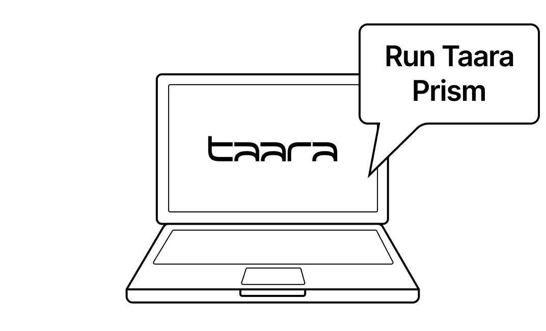
Download Taara Prism from the Taara Partner Portal at partner.taaraconnect.com and connect to the terminal to pre-provision the terminal before heading into the field. This will perform a health check and software check and the pre-provisioning file can be given to an Installer to install the terminal without an internet connection in the field.

Last updated: April 2026